Method for manufacturing resonant device

a technology of resonance device and manufacturing method, which is applied in the direction of turn-sensitive device, impedence network, instruments, etc., can solve the problems of difficult to use gap frequency as an index for processing body, and difficulty in accurately measuring actual resonance frequency, etc., and achieve accurate coupling of vibration

Inactive Publication Date: 2006-08-01
PANASONIC CORP
View PDF11 Cites 8 Cited by
  • Summary
  • Abstract
  • Description
  • Claims
  • Application Information

AI Technical Summary

Benefits of technology

[0007]According to this method, the etching is controlled while frequency characteristics are measured, thus providing a resonant device having a predetermined resonance frequency and a predetermined gap frequency, and having accurate coupling of vibration.

Problems solved by technology

Therefore, it is difficult to measure actual resonance frequencies exactly.
That is, it is difficult to use the gap frequency as an index for processing the body by the foregoing method.

Method used


Image

  • Method for manufacturing resonant device
  • Method for manufacturing resonant device
  • Method for manufacturing resonant device

Examples


exemplary embodiment 1

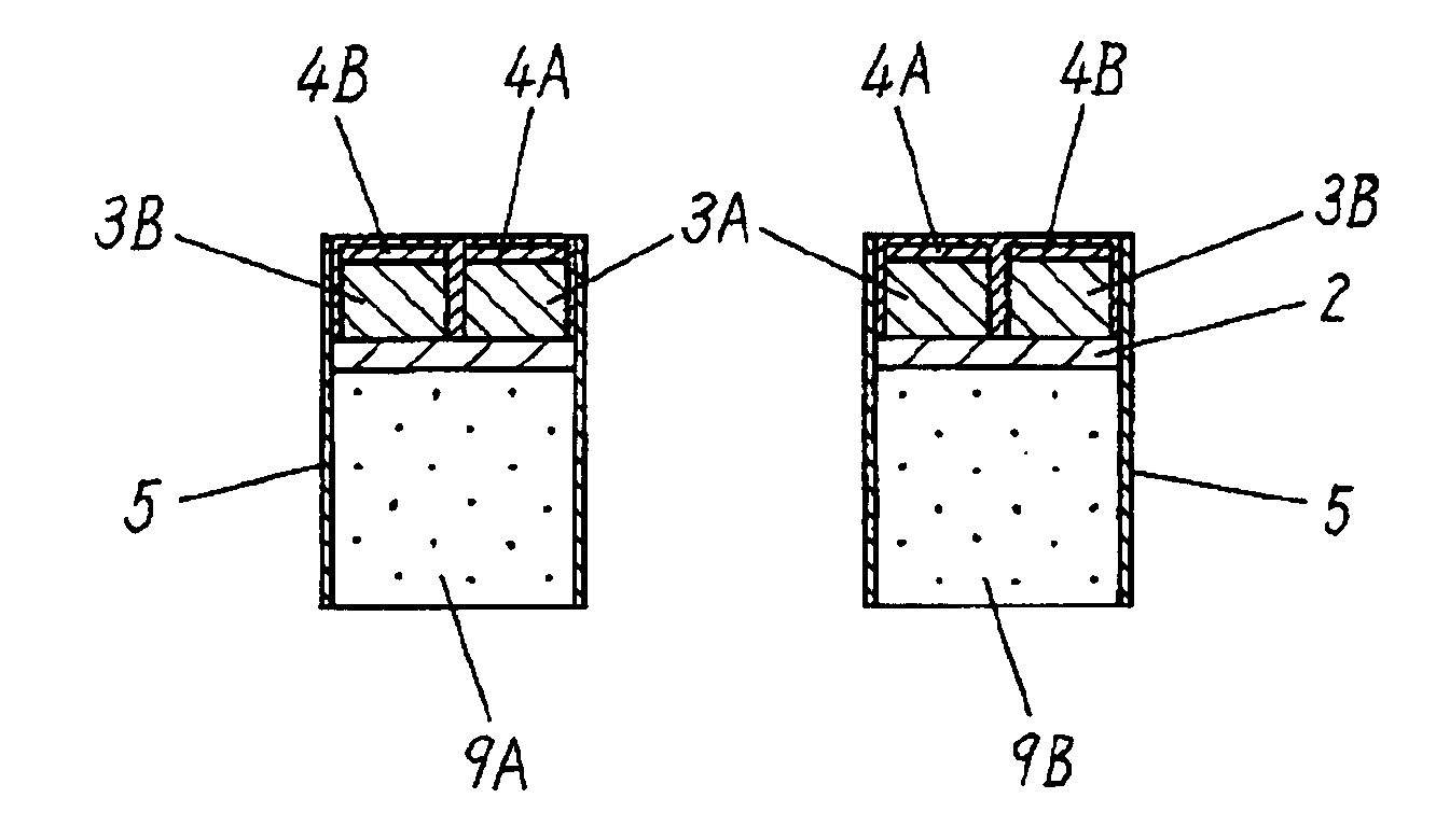
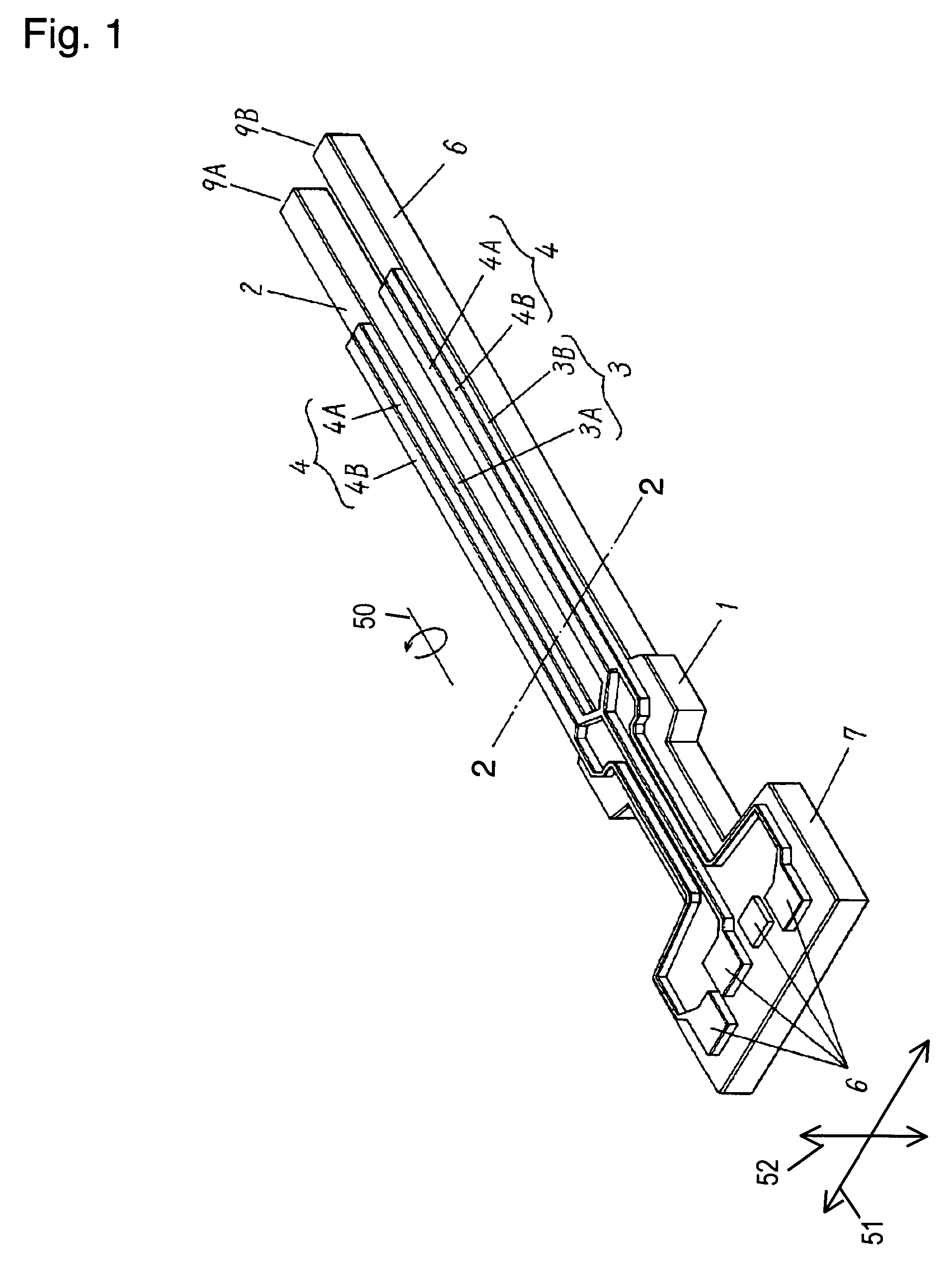
[0023]FIG. 1 is a perspective view of an angular velocity sensor, a resonant device in accordance with Exemplary Embodiments of the present invention. The sensor includes body 1 having a tuning-fork shape and made of silicon, lower electrode 2 on an upper surface of body 1 and made of platinum, driving piezoelectric member 3A and detecting piezoelectric member 3B on an upper surface of lower electrode 2 and made of lead zirconate titanate, driving electrode 4A on an upper surface of driving piezoelectric member 3A, and detecting electrode 4B on an upper surface of detecting piezoelectric member 3B. Lower electrode 2 and upper electrode 4 are connected to an exterior via lead-wires and electrode pad 6 on base 7 of body 1.

[0024]An operation of the angular velocity sensor will be described below with reference to FIG. 1. Upper electrode 4 is separated into driving electrode 4A and detecting electrode 4B. Driving piezoelectric member 3A is located between electrode 4A and lower electrod...

exemplary embodiment 2

[0039]FIG. 14 is a sectional view of a body of an angular velocity sensor in accordance with Exemplary Embodiment 2 of the present invention. The sensor, differently from that of Embodiment 1, has a protective film made of carbon-fluoride polymer formed on an under surface of the body instead of a lateral surface before etching with xenon fluoride gas, as shown in FIG. 14. The protective film causes the xenon fluoride gas to etch exclusively silicon of a lateral surface of the body. As a result, only a resonance frequency in a driving direction decreases according to progress of the etching. This allows a gap frequency between resonant frequencies of a driving direction and a detecting direction to be adjusted.

exemplary embodiment 3

[0040]FIG. 15 is a sectional view of a body of an angular velocity sensor in accordance with Exemplary Embodiment 3 of the present invention. The sensor, differently from those of Embodiments 1 and 2, has a protective film made of carbon fluoride polymer formed not only on a lateral surface or an under surface of the body, but also on portions of both the lateral surface and the under surface. Portions of corners of the body are exposed, as shown in FIG. 15. In FIG. 15, the body may have a cross-section having a parallelogram shape, and have corners having acute-angled sections exposed.

[0041]This structure allows xenon fluoride gas to etch these exposed corners exclusively. In the body having the cross section having the parallelogram shape, respective vibrations in a driving direction and a detecting direction may be coupled with each other, however, the foregoing structure can cancel this coupling.

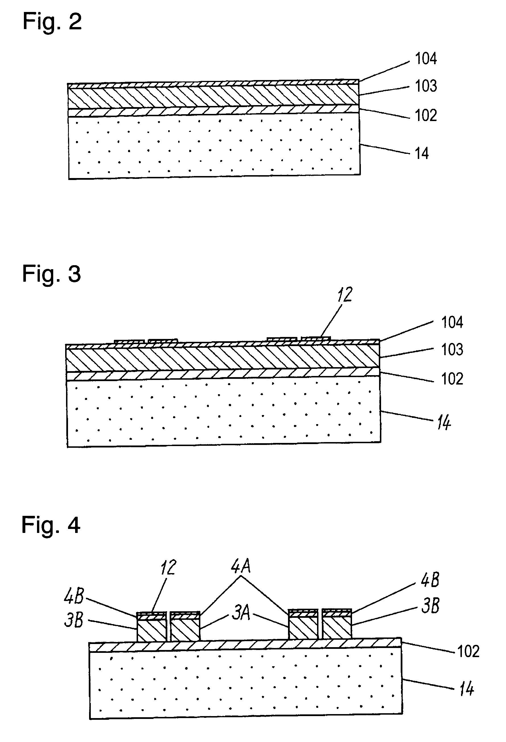
[0042]In the method of manufacturing the resonant device according to the embodiment...


PUM

PropertyMeasurementUnit
resonance frequenciesaaaaaaaaaa
thicknessaaaaaaaaaa

Abstract

A piezoelectric member and an electrode are formed over a silicon substrate. The piezoelectric member and the electrode are patterned by photolithography. The silicon substrate is etched to form a body. A protective film is formed on at least one surface of the body. Another surface having no protective film thereon is etched to obtain a resonant device. The body is etched in its thickness direction accurately while a resonance frequency of the body is measured. The manufacturing processes allow the resonance frequency and a gap frequency of the resonant device to be adjusted to predetermined values.

Description

TECHNICAL FIELD[0001]The present invention relates to a resonant device utilizing mechanical resonance phenomena of substance, for use in, for example, acceleration sensors, angular velocity sensors, resonators, and filters.BACKGROUND ART[0002]U.S. Pat. No. 5,438,231 discloses an angular velocity sensor, a conventional resonant device which includes a body made of non-piezoelectric material, such as silicon, and having a tuning-fork shape, a lower electrode on the body, a piezoelectric member on the lower electrode, and plural upper electrodes on the piezoelectric member. A voltage applied between the lower electrode and the upper electrodes causes the tuning fork-shape body to vibrate. An angular velocity applied to the body from outside during the vibration displaces the body perpendicularly to a vibrating direction due to Coriolis force. The displacement generates a voltage between the upper electrodes and the lower electrode, and this voltage is measured as a displacement, hence...

Claims


Application Information

Patent Timeline
Patent Type & Authority Patents(United States)
IPC IPC(8): B44C1/22B44C1/00G01C19/56G01C19/5628H01L41/08H01L41/22H01L41/23H01L41/332H03H3/02H03H9/21
CPCG01C19/5621H03H9/21G01C19/5628H03H2003/026
Inventor NAKATANI, MASAYATAJIKA, HIROFUMI
Owner PANASONIC CORP
Why Eureka
Try Eureka