Ventilation device

a technology of ventilation device and air intake valve, which is applied in the direction of functional valve types, machines/engines, transportation and packaging, etc., can solve the problems of disturbing the occupant of the vehicle, and achieve the effect of preventing the same from fluttering

Inactive Publication Date: 2009-04-23
ILLINOIS TOOL WORKS INC
View PDF24 Cites 9 Cited by
  • Summary
  • Abstract
  • Description
  • Claims
  • Application Information

AI Technical Summary

Benefits of technology

[0009]In accordance with the invention, the non-return flap which is part of the non-return flap element is arranged such that in no position it directly rests against the frame, i.e. in the closed position, in which the non-return flap prevents an ingress of moisture, exhaust gas or dirt into a passenger compartment, it does not rest against the frame. During closure of the non-return flap, the same does not strike against the harder material of the frame, which would cause disturbing noise. The non-return flap rather strikes against the softer material of the non-return flap element. Disturbing noise thereby is prevented. The invention furthermore takes into account that the ventilation device is decoupled from a vehicle component on which it is mounted. In accordance with the invention, the ventilation device engages the vehicle component with a part which is made of the softer material component. Thus, the ventilation device is decoupled from the vehicle component, which in particular is a sheet metal component. Due to the decoupling of the ventilation device from the vehicle component, no vibrations resulting from the movement of the non-return flap are transmitted to the vehicle component.

Problems solved by technology

There is produced noise which is disturbing for a vehicle occupant.
A further disadvantage of known ventilation devices is the fact that the same are not decoupled from t he vehicle body, so that vibrations resulting from the movement of the non-return flap can be transmitted to the vehicle body.

Method used


Image

  • Ventilation device
  • Ventilation device
  • Ventilation device

Examples


first embodiment

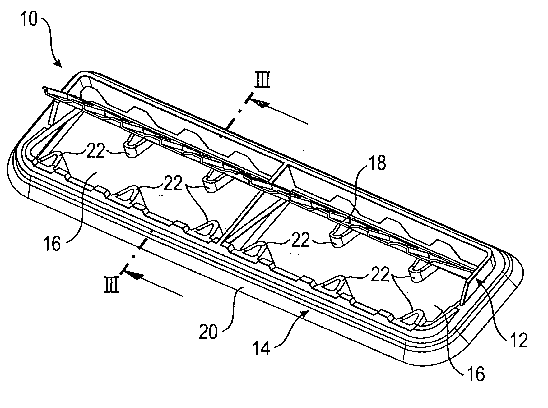
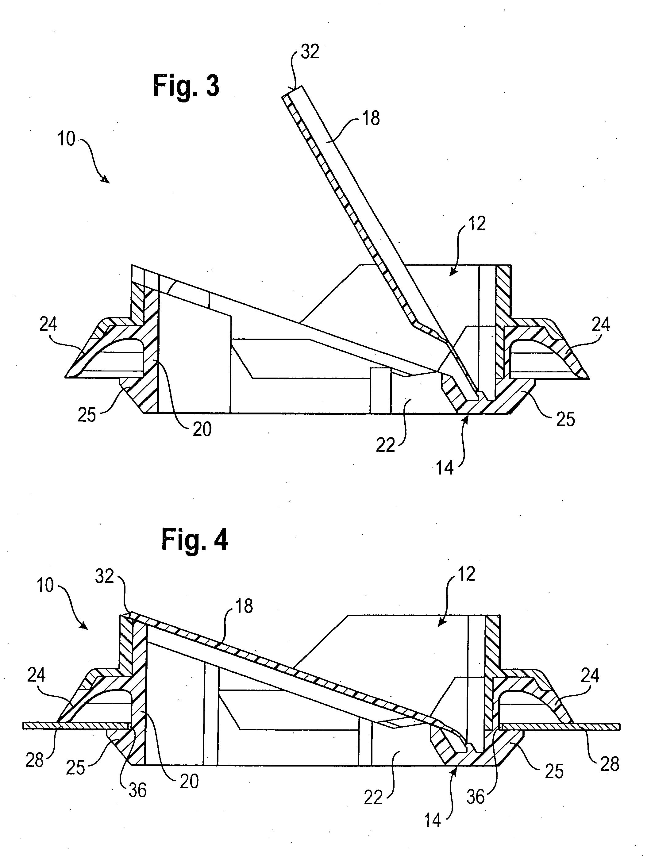
[0031]FIGS. 1 to 8 show a ventilation device 10 in accordance with a The ventilation device 10 consists of a frame 12 (see in particular FIGS. 7 and 8) made of a first material component and a non-return flap element 14 (see in particular FIGS. 5 and 6) made of a second material component. The first material component, of which the frame 12 is made, is harder than the second material component, of which the non-return flap element 14 is formed. The frame 12 thus serves to reinforce the ventilation device 10.

[0032]The frame 12 is formed like a grid and includes two outflow openings 16. The outflow openings 16 can be covered or closed by a non-return flap 18, which is part of the non-return flap element 14.

[0033]The non-return flap element 14 consists of a grid-like frame member 20 and of the non-return flap 18. The grid-like frame member 20 has two outflow openings, which correspond to the outflow openings 16 of the frame 12 and in the assembled condition are aligned with the same.

[...

second embodiment

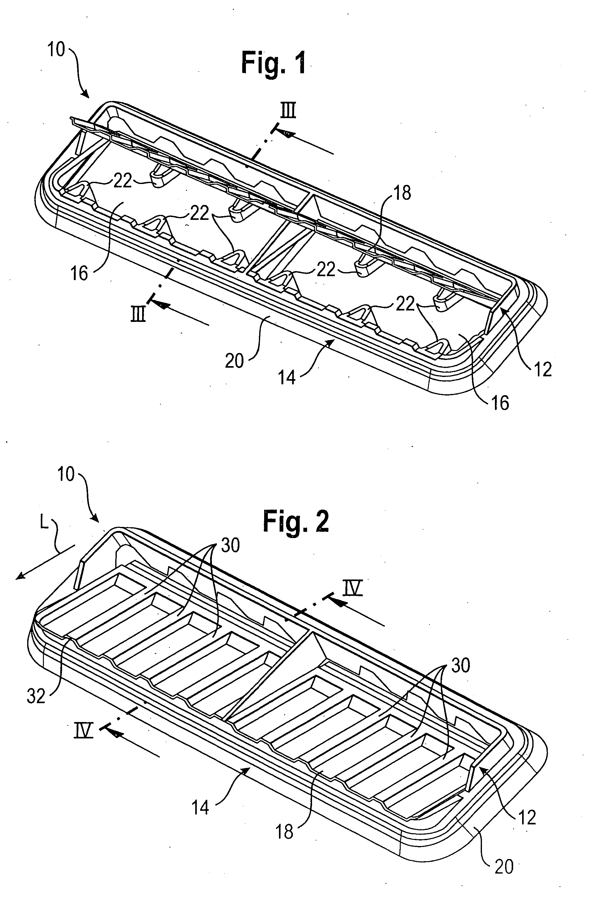
[0044]In FIGS. 9 to 14, a second embodiment is shown.

[0045]The same only differs from the embodiment shown in FIGS. 1 to 8 in that the reinforcement ribs 30, which are formed on the non-return flap 18, do not extend up to the edge 32. The reinforcement ribs 30 end at a distance from the edge 32. The surface of the non-return flap element 14, against which the non-return flap 18 rests in the closed condition and which is provided with the reference numeral 38, therefore is formed flat (i.e. without elevations or depressions).


PUM


Abstract

A ventilation device has a frame (12) made of a first material component, and a non-return flap element (14) made of a second material component, wherein the first material component is harder than the second material component. The non-return flap element (14) includes a movable non-return flap (18), which is arranged such that it exclusively rests against the non-return flap element (14) or the ventilation device (10) is mountable on a vehicle component (28), wherein that part of the ventilation device (10) which engages the vehicle component (28) is part of the non-return flap element (14).

Description

FIELD OF THE INVENTION [0001]This invention relates to a ventilation device, in particular for venting a passenger compartment.BACKGROUND OF THE INVENTION[0002]Ventilation devices are known that comprise a frame made of a first material component and a non-return flap element made of a second material component, wherein the first material component is harder than the second material component.[0003]A ventilation device provides for discharging the air supplied to the passenger compartment via a ventilation system. The ventilation device has a frame, which receives at least one non-return flap. When no air flows out of the passenger compartment, the non-return flap rests against the frame, so that an ingress of moisture, exhaust gas or dirt into the passenger compartment is prevented. It is known to manufacture such ventilation devices from two components, wherein the frame is made of a harder material component, whereas the non-return flap is formed of a softer material component. W...

Claims


Application Information

Patent Timeline
Patent Type & Authority Applications(United States)
IPC IPC(8): B60H1/24
CPCB60H1/249B60H1/246F16K15/031F01N1/14B60H1/24B61D27/00B60H1/00
Inventor LOEWE, HUBERT
Owner ILLINOIS TOOL WORKS INC
Why Eureka
Try Eureka