Filter-Equipped Microplate
- Summary
- Abstract
- Description
- Claims
- Application Information
AI Technical Summary
Benefits of technology
Problems solved by technology
Method used
Image
Examples
example 1
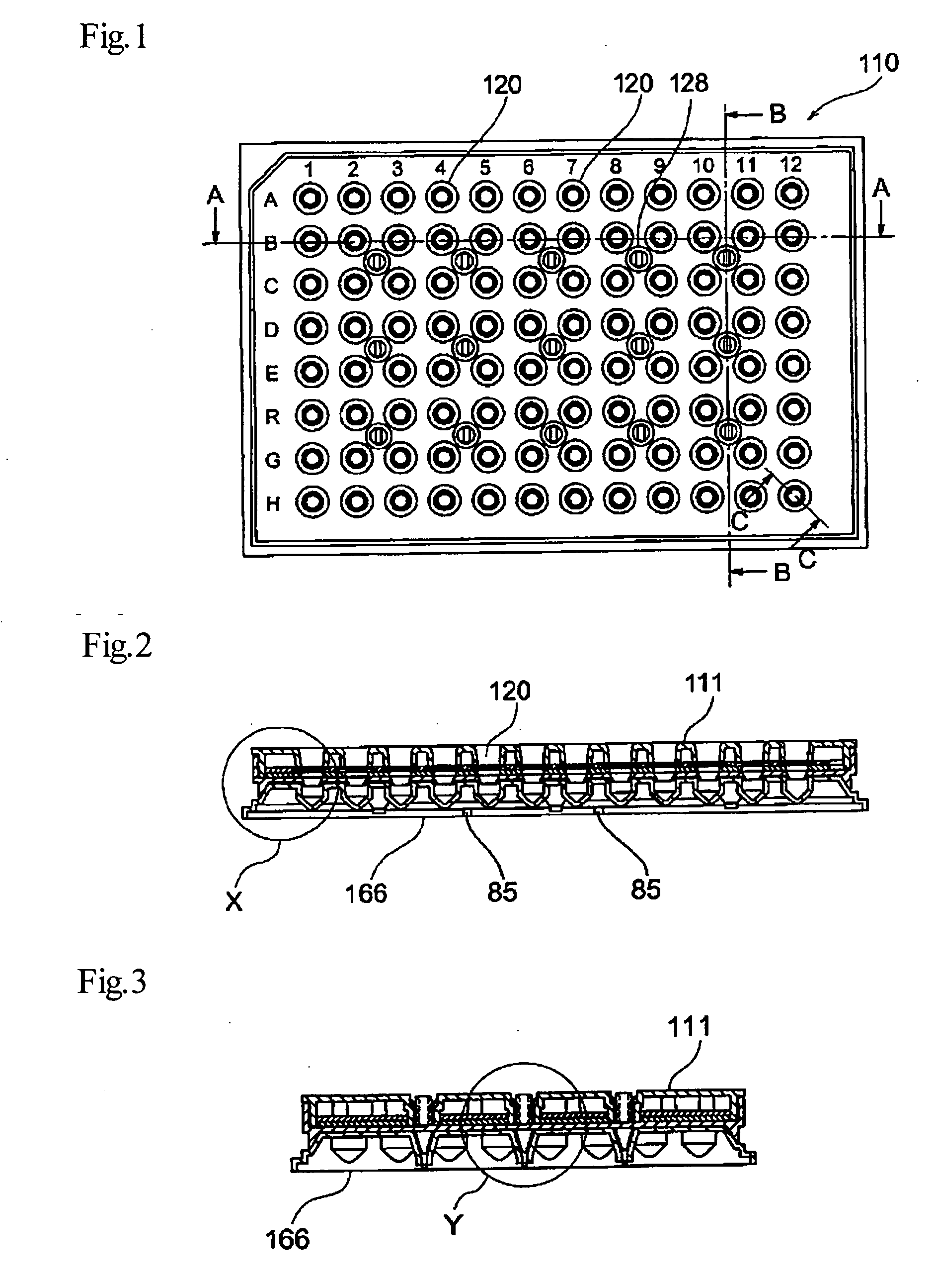
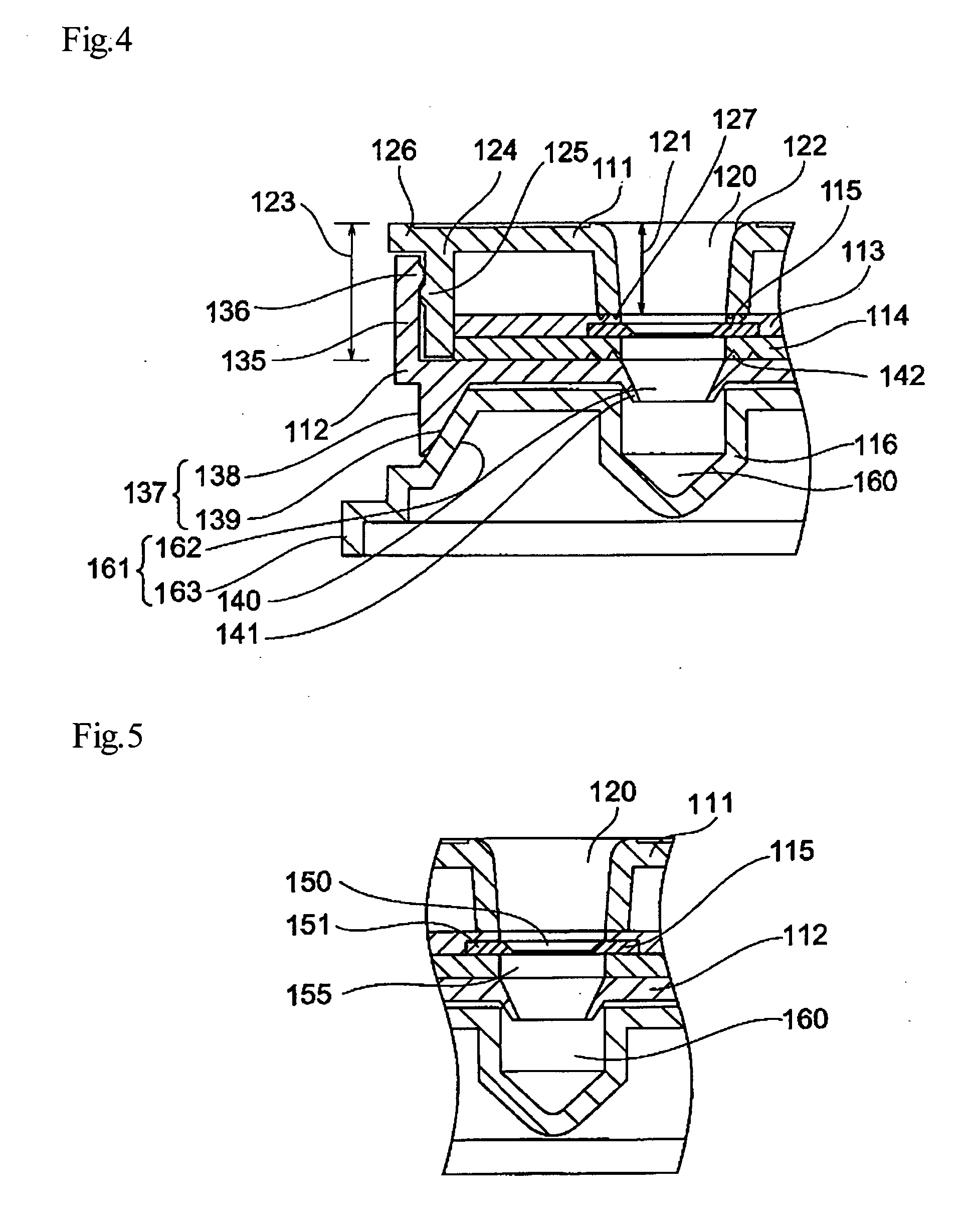
[0192]FIG. 1 is an enlarged plan view of a filter-equipped microplate 110 according to one embodiment of the device of the invention. The microplate has a rectangular-shaped surface as shown in the drawing, and an overall cuboid form with approximate dimensions of, for example, long side (120-150 mm)×short side (80-100 mm)×thickness (10-20 mm). However, one skilled in the art will readily appreciate that the dimensions and shape can be varied according to the purpose and requirements. The filter-equipped microplate 110 of the invention may therefore have a surface with a circular or elliptical shape, for example, instead of a rectangular or other quadrilateral shape as shown in the drawing. However, a rectangular shape is assumed in the following example. The microplate 110 has a plurality of openings 120 formed on the front side, i.e. the top surface (a total of 12×8=96 in FIG. 1), and a culture solution (for example, a substance to be tested such as sampled blood) is supplied into...
example 2
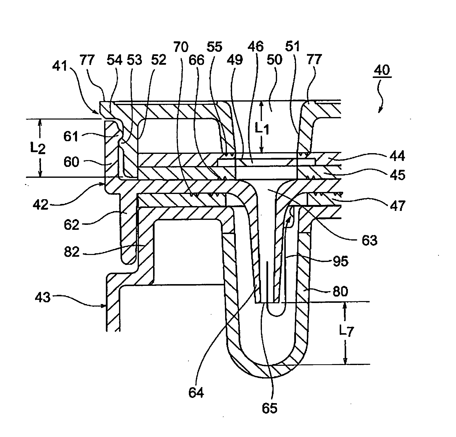
[0228]FIG. 7 is a plan view of a filter-equipped microplate 40 according to the invention. The microplate 40 has a rectangular-shaped surface as shown in the drawing, and an overall cuboid form with approximate dimensions of, for example, long side (120-150 mm)×short side (80-100 mm)×thickness (10-30 mm). However, one skilled in the art will readily understand that the dimensions and shape can be varied according to the purpose and requirements. The filter-equipped microplate 40 of the invention may, therefore, have a surface with a circular or elliptical shape, for example, instead of a rectangular or other quadrilateral shape as shown in FIG. 7. However, a rectangular shape is assumed in the following description. The microplate 40 has a plurality of openings 50 formed on the front side, i.e. the top surface (a total of 12×8=96 in FIG. 7), and a culture solution (for example, a substance to be tested such as sampled blood) is supplied into the microplate 40 through the openings 50...
example 3
[0268]Example 3 according to the invention will now be explained with reference to FIG. 41. Example 3 shown in FIG. 41 is similar to Example 2 described above, and therefore only the aspects differing from that example will be explained here. In FIG. 41, the elements and sections similar to the example described above are indicated by the same numbers, with the letter “A”. As clearly seen by the example shown in FIG. 41, the elements composing the FIG. 41 have slightly different shapes from the elements shown in the previous drawings, particularly FIG. 9, but the basic structures of the respective elements are essentially identical to those of the previous examples and merely constitute modifications that are very easily understood by one skilled in the art, and therefore detailed illustrations of each of the constituent elements of Example 3 are omitted.
[0269]In a filter-equipped microplate 40A shown in FIG. 41, a flange standing section 86 rises vertically upward from a flange 54A...
PUM
| Property | Measurement | Unit |
|---|---|---|
| Current | aaaaa | aaaaa |
| Current | aaaaa | aaaaa |
| Current | aaaaa | aaaaa |
Abstract
Description
Claims
Application Information
 - R&D
- Intellectual Property
- Life Sciences
- Materials
- Tech Scout
- Unparalleled Data Quality
- Higher Quality Content
- 60% Fewer Hallucinations
Browse by: Latest US Patents, China's latest patents, Technical Efficacy Thesaurus, Application Domain, Technology Topic, Popular Technical Reports.
© 2025 PatSnap. All rights reserved.Legal|Privacy policy|Modern Slavery Act Transparency Statement|Sitemap|About US| Contact US: help@patsnap.com


