Reverse engineering based coil spring design method

a design method and coil spring technology, applied in the field of general coils, can solve the problems of increasing the pitch angle of coil springs, unable to provide design results with sufficient accuracy, and difficult to duplicate the same design every tim

Active Publication Date: 2009-04-23
NHK SPRING CO LTD
View PDF6 Cites 14 Cited by
  • Summary
  • Abstract
  • Description
  • Claims
  • Application Information

AI Technical Summary

Problems solved by technology

As a result, the pitch angle of coil springs increased and the statics based simple calculations no longer provided design results with sufficient accuracy.
Because of this, the resultant free profile depends on the individual designer and it is difficult to duplicate the same design every time, even by the same designer with the same requirements.
While the FEA based coil spring design method provides more ability for problem assessment at the design stage, it exacerbates design difficulties and promotes designer-dependent designs.

Method used


Image

  • Reverse engineering based coil spring design method
  • Reverse engineering based coil spring design method
  • Reverse engineering based coil spring design method

Examples


Embodiment Construction

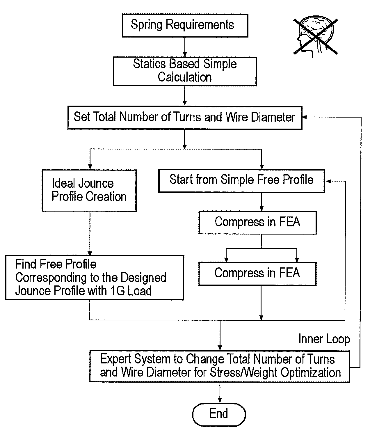
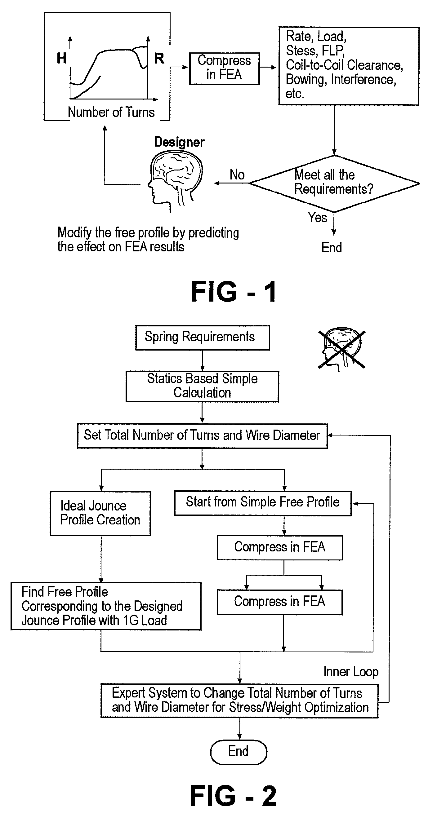
[0041]The present invention is directed to a method for the automated, optimized and designer-independent design of coil springs. The method of the present invention involves a new concept for FEA based coil spring design that utilizes a reverse engineering based concept that involves first designing a desired jounce profile, which is typically an output in the conventional FEA based design, and then reversely determining the corresponding free profile necessary for manufacturing a spring having desired performance specifications. As used herein, Jounce height is the height of a spring when the spring is compressed the most and Jounce profile is the spring profile at jounce height.

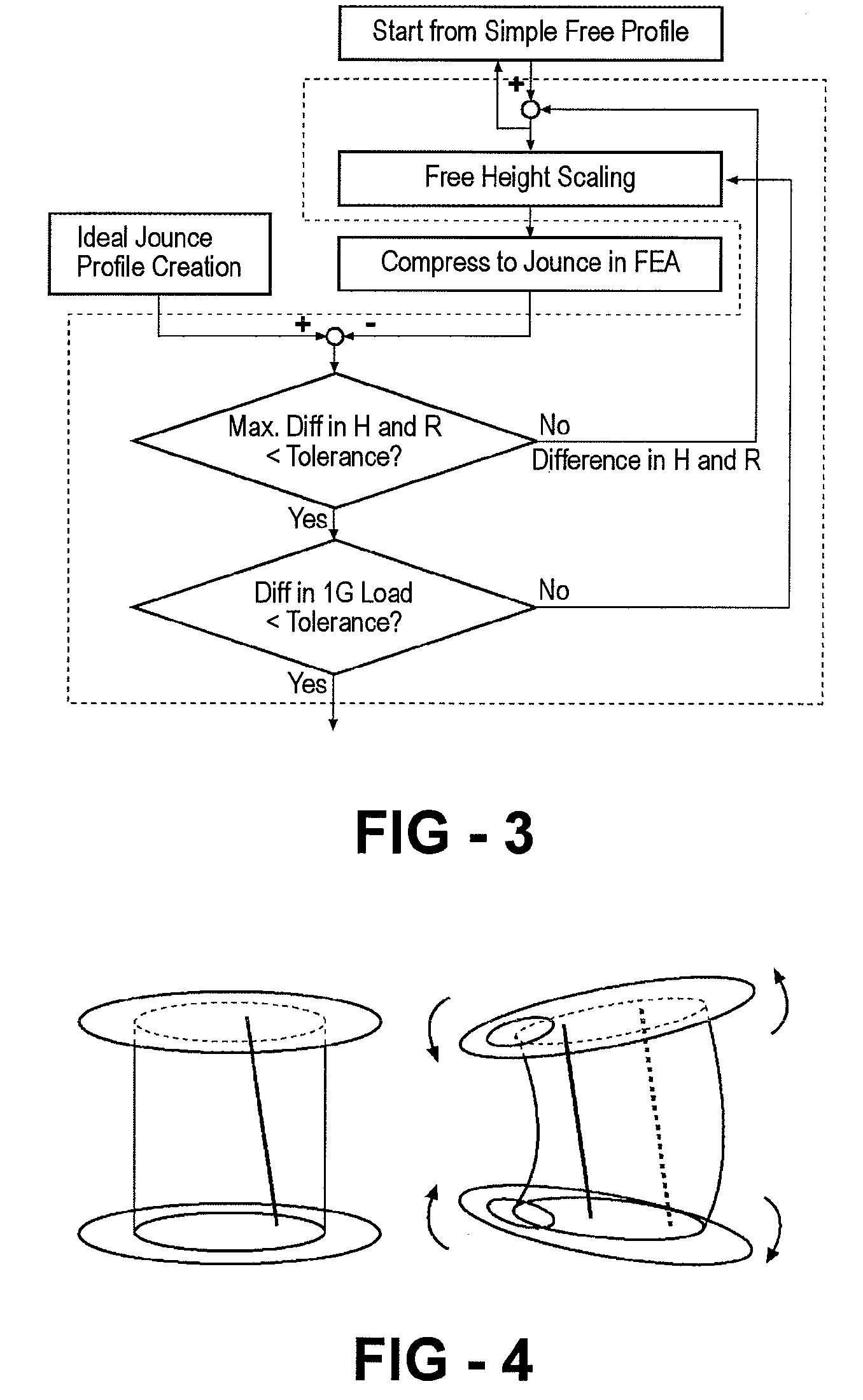
[0042]According to the present invention the ideal deformed spring profile is designed first and its corresponding unique free profile is then reversely determined by automated FEA iterations in order to satisfy the design / specification requirements. By scanning the total number of turns in a certain range...


PUM


Abstract

A finite element analysis (FEA) based coil spring design method that utilizes a reverse engineering based concept. The method involves first designing a desired jounce profile, which is typically an output in the conventional FEA based design, and then reversely determining the corresponding free profile necessary for manufacturing a spring having desired performance specifications.

Description

TECHNICAL FIELD[0001]The present invention relates to general coil. More particularly, the present invention is directed to a method for the automated, optimized and designer-independent design of coil springs, which produces ideal spring shape.BACKGROUND ART[0002]Traditionally, coil springs are designed based upon simple statics with Wahl's correction factor to compensate stress for the effect of curvature. However, this theory was derived with an assumption of zero pitch angle throughout the spring. As high strength materials were developed, coil springs were intentionally designed with fewer turns to efficiently utilize the capability of the newer high strength materials. As a result, the pitch angle of coil springs increased and the statics based simple calculations no longer provided design results with sufficient accuracy.[0003]In 1990, Finite Element Analysis (FEA) based coil spring design, including an estimation of the spring Force Line Position (FLP), became popular as a w...

Claims


Application Information

Patent Timeline
Patent Type & Authority Applications(United States)
IPC IPC(8): G06G7/48B60G11/14
CPCB60G11/15G06F17/5018F16F1/04B60G2202/12G06F30/23
Inventor NISHIZAWA, SHINICHISAKAI, TADASHI
Owner NHK SPRING CO LTD
Why Eureka
Try Eureka