Method and system for simulating aero-optical effect

An aero-optics and effect technology, applied in the field of optics, can solve the problems of unfavorable distorted image restoration research, fast change frequency of wavefront error, and inability to obtain distorted image data, etc.

Inactive Publication Date: 2013-08-14
BEIJING INSTITUTE OF TECHNOLOGYGY +1
View PDF6 Cites 51 Cited by
  • Summary
  • Abstract
  • Description
  • Claims
  • Application Information

AI Technical Summary

Problems solved by technology

Since the computer simulation does not include the actual optical system and imaging detector, the distorted image data of the actual imaging detector cannot be obtained, which is not conducive to the subsequent research on the restorati...

Method used


Image

  • Method and system for simulating aero-optical effect
  • Method and system for simulating aero-optical effect
  • Method and system for simulating aero-optical effect

Examples


Embodiment Construction

[0033] In order to make the object, technical solution and advantages of the present invention more clearly, the present invention will be further described in detail below in conjunction with the accompanying drawings and specific embodiments.

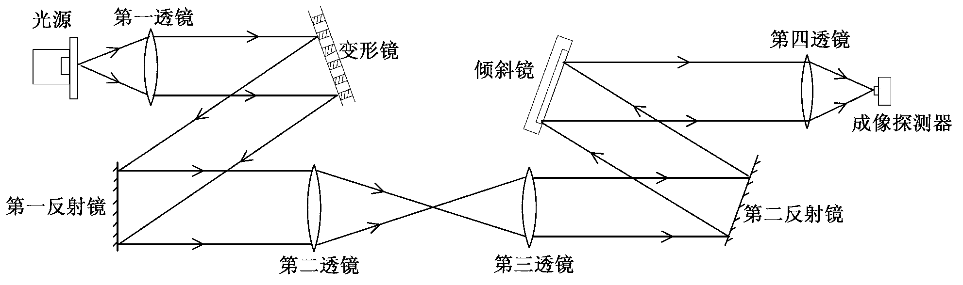
[0034] In the embodiment of the present invention, multi-frame wavefront error data caused by thermo-optical effect, optical window deformation and elastic-optic effect are obtained through finite element analysis, and the simulation of aero-optical effect is realized through deformable mirror and tilted mirror, and then aerodynamic Distorted image data under the influence of optical effects.

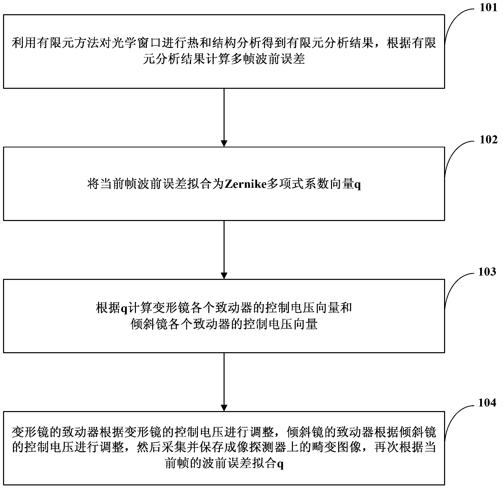
[0035] See attached figure 1 is a schematic flow chart of a method for simulating aero-optical effects, specifically including the following steps:

[0036] 101. Use the finite element method to conduct thermal and mechanical analysis of the optical window, and calculate the multi-frame wavefront error caused by the thermo-optic effect, optica...


PUM


Abstract

The invention relates to a method for simulating an aero-optical effect. The method comprises the steps of conducting thermal and structural analysis to an optical window by adopting a finite element analysis method to obtain a finite element analysis result, and calculating multi-frame wave-front errors according to the finite element analysis result; fitting the current frame wave-front error to be a Zernike polynomial coefficient vector q; calculating control voltage vectors of all actuators of a deformable mirror and control voltage vectors of all actuators of a tilting mirror according to the q; and adjusting the actuators of the deformable mirror according to the control voltage of the deformable mirror, adjusting the actuators of the tiling mirror according to the control voltage of the tiling mirror, acquiring and saving distorted images on an imaging detector and again fitting the q according to the current frame wave-front error. The invention additionally discloses a system for simulating the aero-optical effect. By using the method and the system provided by the embodiment of the invention, dynamic distorted image data under the influence of the aero-optical effect can be obtained and experimental conditions are provided for researches on the correction of the aero-optical effect.

Description

technical field [0001] The present application relates to the field of optical technology, and more specifically, to a method and system for simulating aero-optical effects. Background technique [0002] When an aircraft with an optical imaging detection and guidance system flies in the atmosphere at high speed, a complex flow field is formed between the optical window and the incoming flow, causing thermal radiation and image transmission interference to the optical imaging detection system, causing the target image to shift and shake and blurring, this effect is called aero-optical effect. [0003] The aero-optical effect has a negative impact on the guidance system, reduces the ability of the seeker to detect, track and identify the target, and affects the accuracy of the terminal guidance. When studying how to overcome the influence of aero-optic effects on the imaging detection of guidance systems, it is first necessary to obtain distorted image data by simulating the ...

Claims


Application Information

Patent Timeline
IPC IPC(8): G09B23/12
Inventor 董冰胡新奇宋杰赵宏鸣杜惠杰虞红
Owner BEIJING INSTITUTE OF TECHNOLOGYGY
Why Eureka
Try Eureka