Fully Insulated Fuse Test and Ground Device

a fully-insulated, fuse-free technology, applied in the direction of coupling device connection, connection contact member material, instruments, etc., can solve the problems of reducing the safety of operators, so as to achieve the effect of improving safety

Active Publication Date: 2009-04-30
EATON INTELLIGENT POWER LIMITED
View PDF99 Cites 16 Cited by
  • Summary
  • Abstract
  • Description
  • Claims
  • Application Information

AI Technical Summary

Benefits of technology

[0006]A fully insulated fuse test and ground device provides improved safety by incorporating the eye, ground lead and conductive connections within an insulated housing. The tool als

Problems solved by technology

Unfortunately, conventional grounding devices, such as grounding elbows without fuses, have drawbacks.
These grounding devices do not include an active element that prevents fault close.
Therefore, the conventional grounding devices do not include fault close protection, are not able to prevent a fault and thus, are subject to a fault close.
If an operator were to mistakenly position the conventional grounding device on an energized bushing a fault close and explosion would occur that can cause serious harm to the operator.
However, the alternative grounding device also has drawbacks.
The exposed portions of this

Method used


Image

  • Fully Insulated Fuse Test and Ground Device
  • Fully Insulated Fuse Test and Ground Device
  • Fully Insulated Fuse Test and Ground Device

Examples


Embodiment Construction

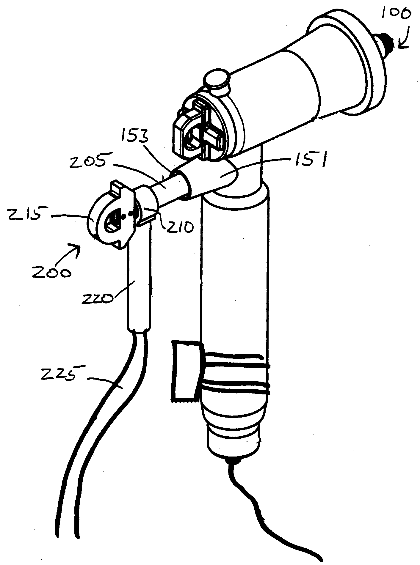
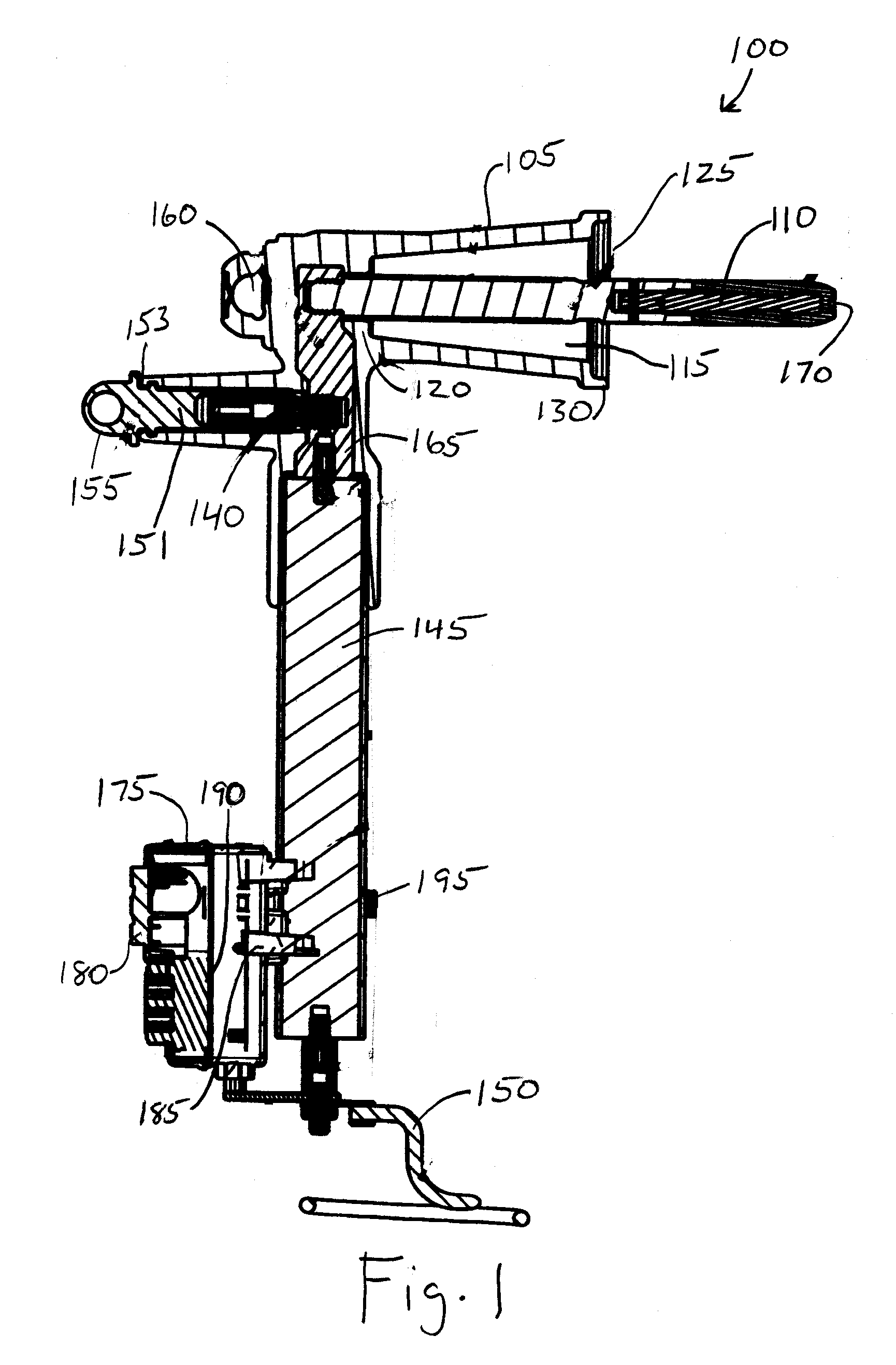
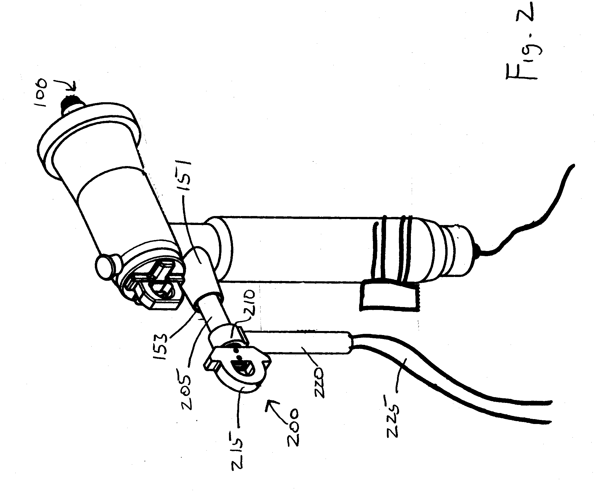
[0018]The present invention is directed to a fully insulated fuse test and ground device. The present invention is also directed to a grounding plug that may be used in conjunction with the fully insulated fuse test and ground device to provide a permanent ground to the device. The present invention is also directed to methods of providing a permanent ground to a fully insulated fuse test and ground device through the use of a grounding plug. Exemplary embodiments of the invention can be more readily understood by reference to the accompanying figures.

[0019]Exemplary embodiments of the present invention include a fully insulated fuse test and ground device and a grounding plug used in conjunction therewith to provide a permanent ground to the device when used in a power distribution environment. However, it should be apparent that there could be many different ways of implementing the invention in an power distribution environment, and the invention should not be construed as limite...


PUM

PropertyMeasurementUnit
Forceaaaaaaaaaa
Electrical conductivityaaaaaaaaaa
Diameteraaaaaaaaaa

Abstract

A fuse test and ground device includes an insulated housing with a bore that extends from the front of the housing towards the rear of the housing. An electrical contact is disposed partially within the bore. A current interrupter, such as a fuse, is electrically connected between the contact and a testing ground lead. An eye, having it's surface insulated by the housing, can be attached to the housing and provide a connection point for manipulation of the device. A grounding bore extends from a second aperture into the housing and provides an electrical connection to the contact. A grounding plug can be connected to ground on one end and inserted into the grounding bore to create a permanent ground for the device. An annunciator is connected to the current interrupter such that the annunciator provides an indication when a current flows through the current interrupter.

Description

FIELD OF THE INVENTION[0001]The present invention relates generally to the field of electric power distribution systems. More particularly, the invention relates to a combined grounding device and testing tool for use in an electric power distribution system.BACKGROUND OF THE INVENTION[0002]In power distribution systems, high-voltage separable connectors interconnect various forms of electrical equipment, such as transformers, switchgear, distribution cables, and the like. These connectors typically have an elbow component that mates with a bushing component. The electrical equipment often needs to be grounded. For example, the electrical equipment must be grounded for repair or servicing, or when being moved to reconfigure or isolate parts of the system. In these examples, a grounding device (e.g., a grounding elbow) is typically used to provide a visible ground.[0003]Unfortunately, conventional grounding devices, such as grounding elbows without fuses, have drawbacks. These ground...

Claims


Application Information

Patent Timeline
IPC IPC(8): G01R31/28
CPCG01R31/07Y10T29/49826Y10S439/921H01H85/30G01R31/74
Inventor HUGHES, DAVID CHARLESWHITMORE, STEVEN GUY
Owner EATON INTELLIGENT POWER LIMITED
Why Eureka
Try Eureka