

Core Securing Member And Its Structure
a technology of securing member and core, which is applied in the direction of transformer/inductance details, fixed inductances, etc., can solve the problems of lowering space efficiency, increasing costs, and difficult to achieve miniaturization and lightweight of a reactor, so as to reduce the component count of the reactor of the present invention, increase space efficiency, and reduce costs
- Summary
- Abstract
- Description
- Claims
- Application Information
AI Technical Summary
Benefits of technology
Problems solved by technology
Method used
Image

Examples
Embodiment Construction
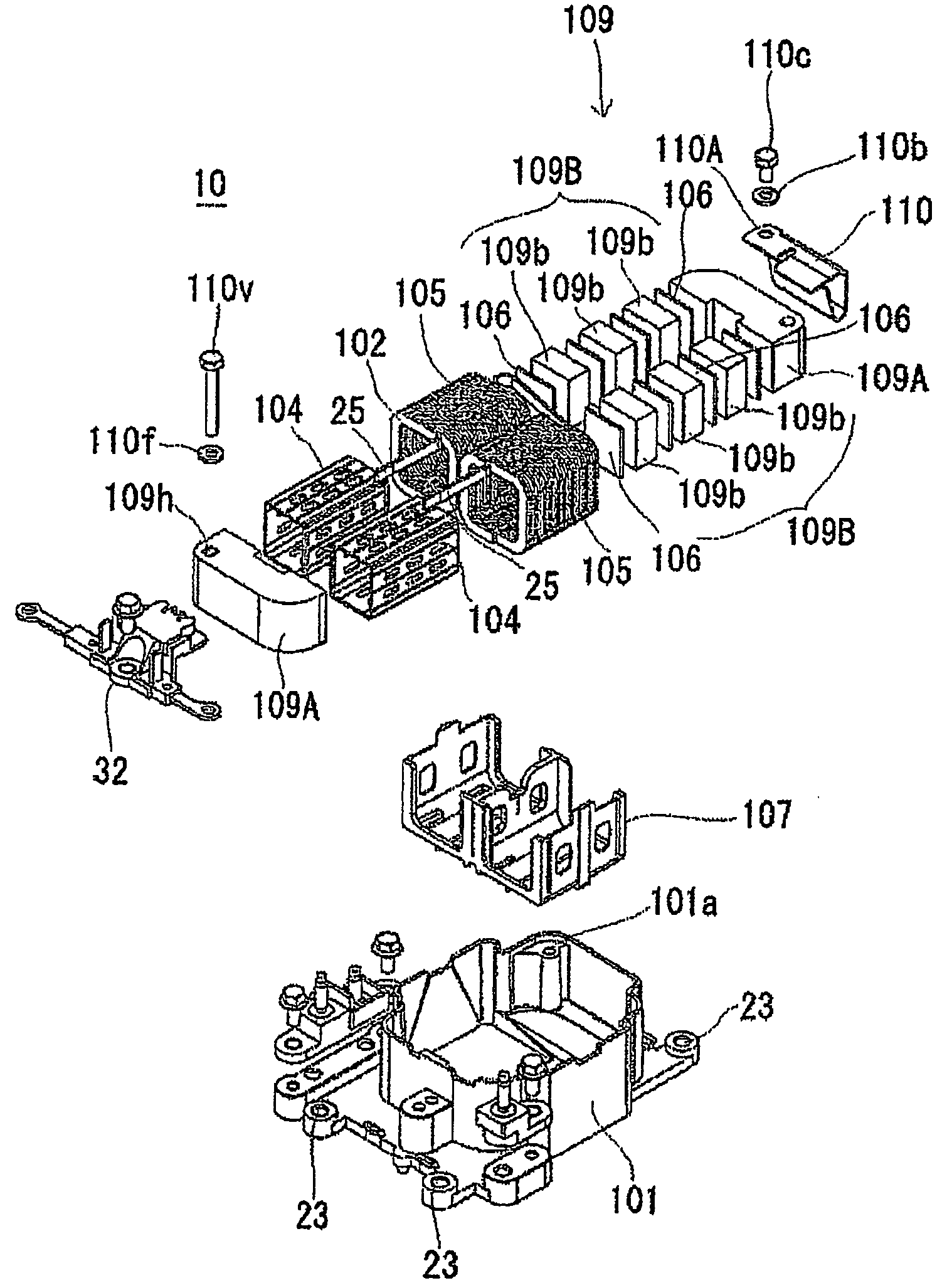
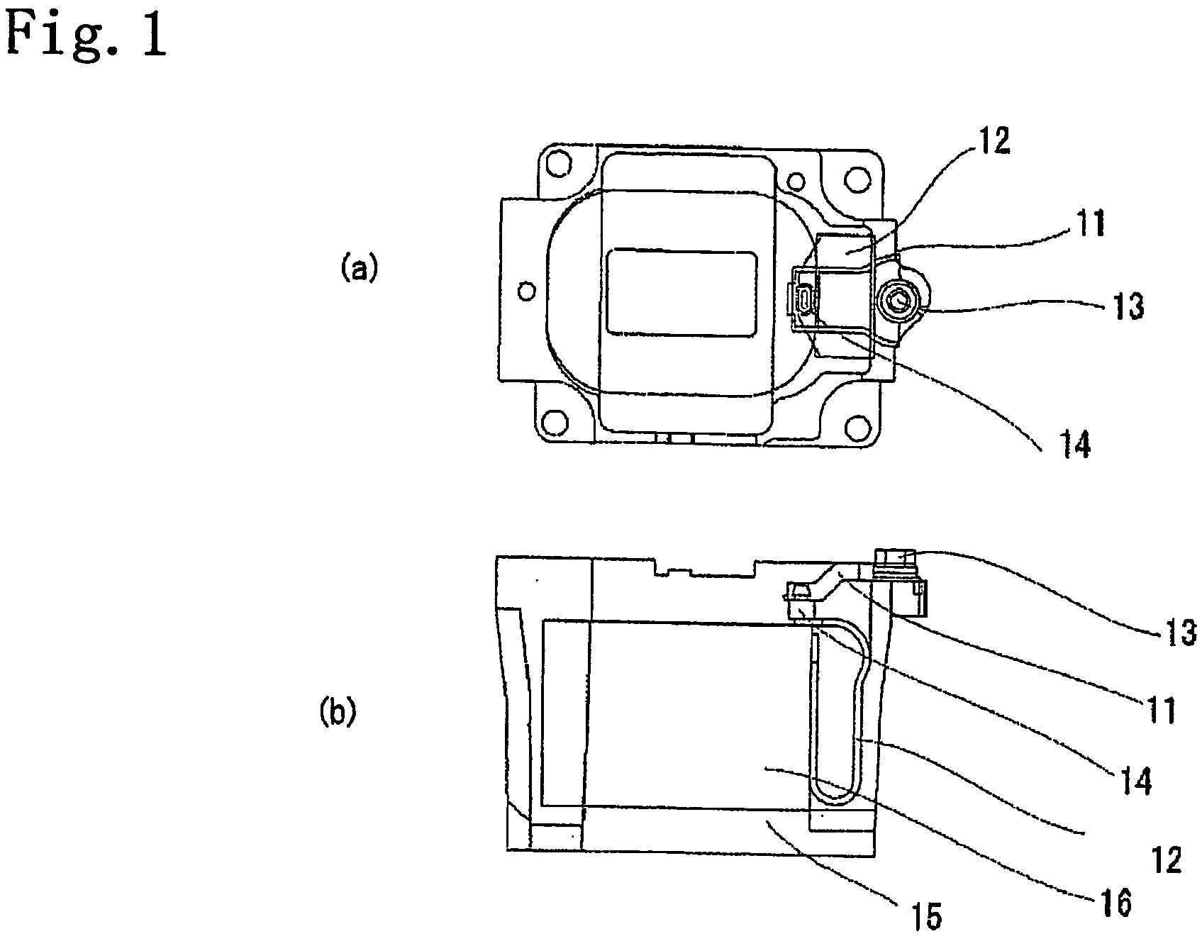
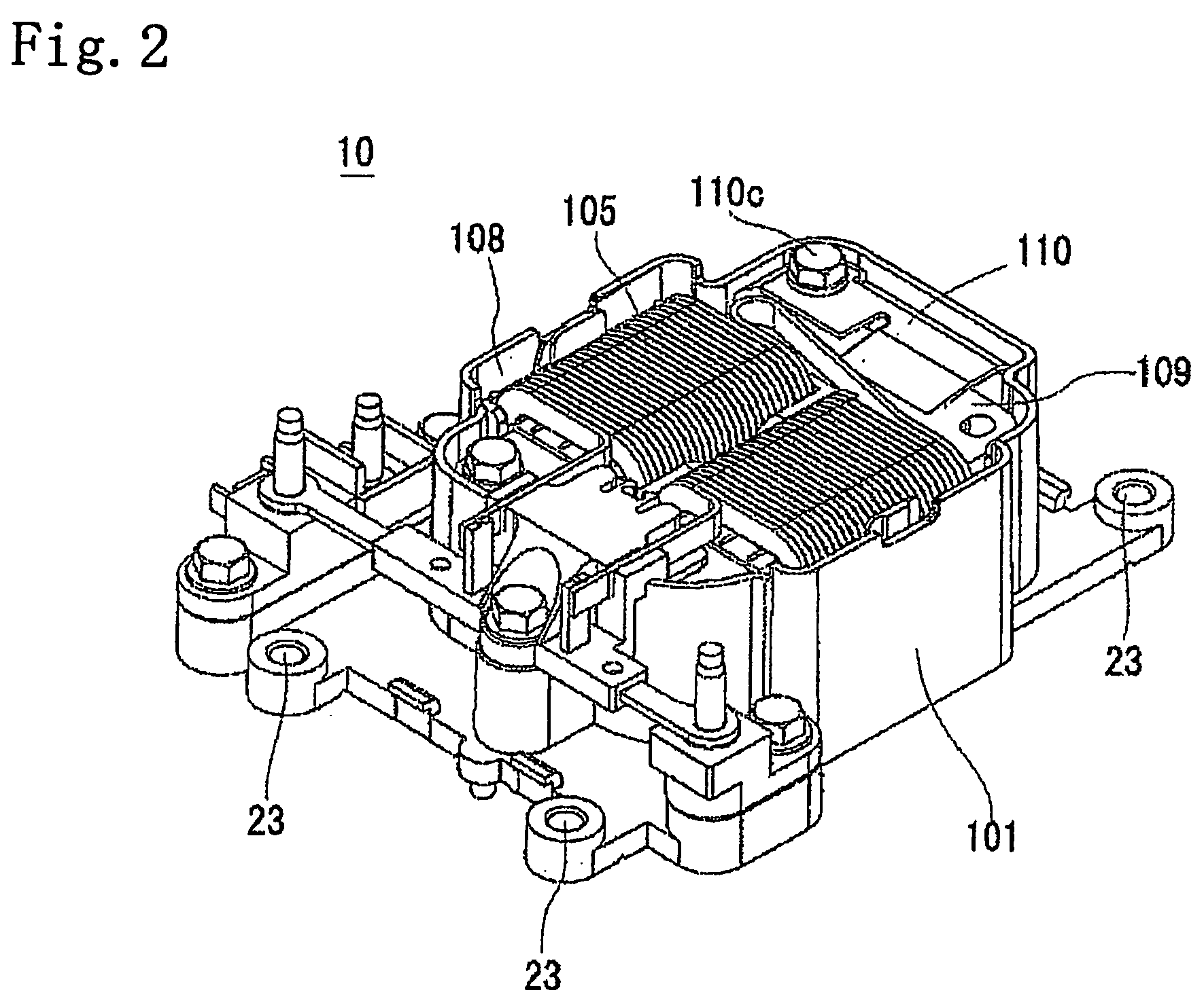
[0020]A core securing member and its structure of an embodiment of the present invention are described in detail by referring to drawings. FIG. 2 is a perspective view of one example of a reactor including a core securing structure of the embodiment of the present invention. FIG. 3 is an exploded perspective view of the reactor shown in FIG. 2. FIG. 4 is a diagram showing a core securing member of the embodiment of the present invention and FIG. 4(a) is its a plan view, FIG. 4(b) is its front view, FIG. 4(c) is its left side view, FIG. 4(d) is its right side view, FIG. 4(e) is its bottom view, FIG. 4(f) is its rear view, and FIG. 4(g) is its perspective view.
[0021]The reactor 10 shown in FIGS. 2 and 3 is used in an electronic circuit having, for example, a forcedly cooling means and is so configured that reactor components formed by winding a winding line 102 around a core 109 (particularly, see FIG. 3) using a winding frame are housed into a thermal conductive reactor case 101 with...
PUM
| Property | Measurement | Unit |
|---|---|---|
| momentum | aaaaa | aaaaa |
| R (curvature | aaaaa | aaaaa |
| inductance | aaaaa | aaaaa |
Abstract
Description
Claims
Application Information