Circuit device and active-matrix display apparatus

a technology of active matrix and display apparatus, which is applied in the direction of instruments, statically indicated devices, etc., can solve the problems of unattainable desired operation, and achieve the effect of high reliability

Inactive Publication Date: 2009-04-30
CANON KK
View PDF58 Cites 17 Cited by
  • Summary
  • Abstract
  • Description
  • Claims
  • Application Information

AI Technical Summary

Benefits of technology

[0028]In accordance with the present invention, at least one of the rises of a plurality of control signals and the falls thereof can occur in a desired sequence without consideration of the characteristics of TFTs and time constant of wiring by generation of a control signal using another control signal propagated through a circuit including a TFT. Accordingly, fine timing control can be performed reliably, and a highly reliable driving circuit that ensures accurate operation and an active-matrix display apparatus that uses the driving circuit can be provided.

Problems solved by technology

Therefore, when it is necessary to supply a plurality of control signals at slightly different times, a problem arises in which the times of the rises of the control signals or the times of the falls thereof may be inverted, and thus a desired operation may be unachievable.

Method used


Image

  • Circuit device and active-matrix display apparatus
  • Circuit device and active-matrix display apparatus
  • Circuit device and active-matrix display apparatus

Examples


first embodiment

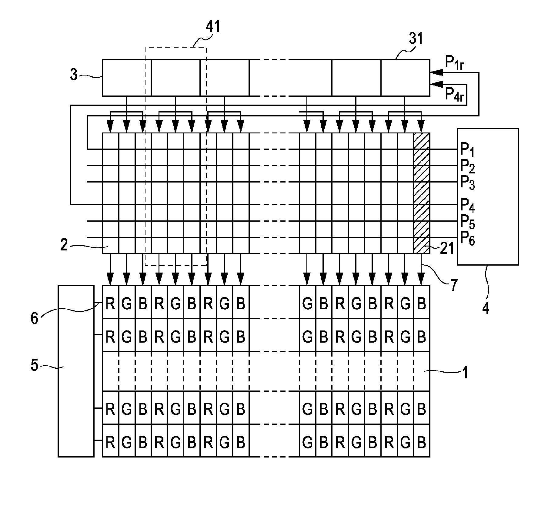
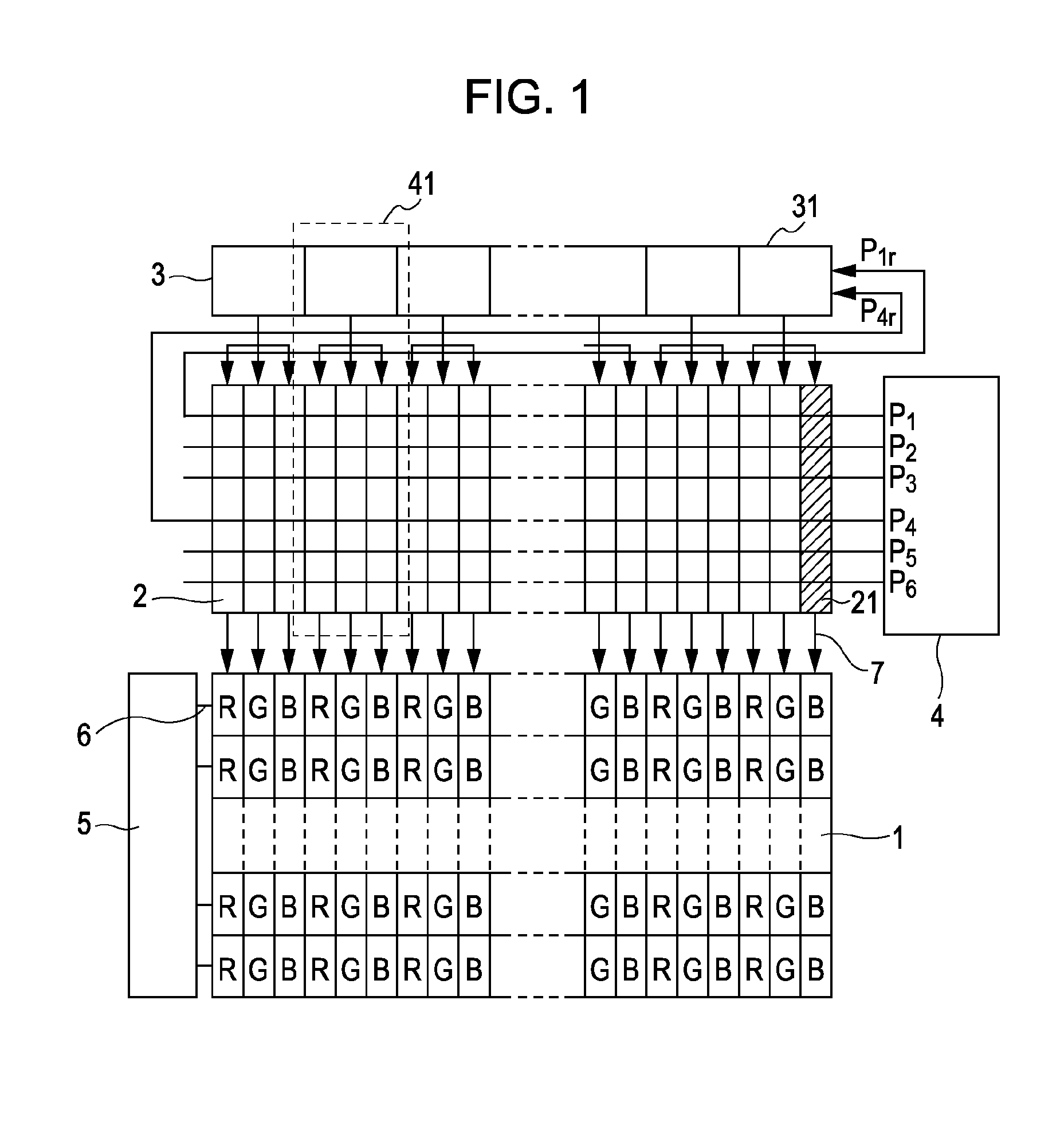
[0045]FIG. 1 illustrates a circuit configuration of a circuit device according to the present embodiment. In FIG. 1, reference numeral 1 represents an image display portion, reference numeral 2 represents a column control circuit group, reference numeral 3 represents a sampling-signal generating circuit, reference numeral 4 represents a control-signal generating circuit, reference numeral 5 represents a row control circuit, reference numeral 6 represents a scanning line (light-emitting period control line), and reference numeral 7 represents a data line. The control-signal generating circuit 4 corresponds to a first circuit included in the circuit device described in the present invention, and the column control circuit group 2 corresponds to a second circuit included in the circuit device described in the present invention.

[0046]In the image display portion 1, a plurality of pixels are arranged in a plane. The pixels are arranged in a matrix in the row and column directions within ...

second embodiment

[0055]The present embodiment is an active-matrix display apparatus including a circuit device similar to that in the first embodiment. FIG. 5 illustrates a circuit configuration of the present embodiment. In FIG. 5, reference numeral 2A represents a column control circuit group, reference numeral 3A represents a sampling-signal generating circuit, and reference numeral 4A represents a control-signal generating circuit. The control-signal generating circuit 4A corresponds to a first circuit, and the column control circuit group 2A corresponds to a second circuit.

[0056]The present embodiment is substantially the same as the first embodiment except that it includes the column control circuit group 2A, the sampling-signal generating circuit 3A, and the control-signal generating circuit 4A in place of the column control circuit group 2, the sampling-signal generating circuit 3, and the control-signal generating circuit 4, respectively.

[0057]FIG. 6 illustrates a configuration of a column ...


PUM


Abstract

A circuit device includes a first circuit including a thin-film transistor and a second circuit including another thin-film transistor. The second circuit is controlled by control signals including a first control signal and a second control signal delayed from the first control signal. The second control signal is generated on the basis of the first control signal which has been propagated through the second circuit.

Description

BACKGROUND OF THE INVENTION[0001]1. Field of the Invention[0002]The present invention relates to a circuit device including a thin-film transistor (hereinafter abbreviated to a TFT). The present invention also relates to an active-matrix display apparatus having a circuit device including a TFT.[0003]2. Description of the Related Art[0004]In recent years, attention is being given to a light-emitting display apparatus using a light-emitting element as a next-generation display apparatus. In particular, a display apparatus using an organic electroluminescent (EL) element, which is a current-controlled light-emitting element whose emission luminance is controlled by a current, i.e., a so-called organic EL display apparatus is known. One type of organic EL display apparatus is an active matrix display apparatus, which uses TFTs in a display region and a peripheral circuit and controls emission of light of organic EL elements by use of the TFTs. One known driving method used in the activ...

Claims


Application Information

Patent Timeline
Patent Type & Authority Applications(United States)
IPC IPC(8): G09G3/30G09G3/36
CPCG09G3/3225G09G3/3283G09G2320/0233G09G2310/0297G09G2320/0209G09G2300/0426
Inventor GODEN, TATSUHITOKAWASAKI, SOMEIISEKI, MASAMI
Owner CANON KK
Why Eureka
Try Eureka