
Reconstructable geometry shadow mapping method

a reconstruction method and geometry technology, applied in the field of graphic processing technology, can solve the problems of aliasing errors and depth bias issues, often occurring perspective aliasing errors, and demanding a lot of fill time for shadow volume technology on hardwar

Active Publication Date: 2009-04-30
VIA TECH INC
View PDF9 Cites 11 Cited by
  • Summary
  • Abstract
  • Description
  • Claims
  • Application Information

AI Technical Summary

Benefits of technology

[0008]Accordingly, the present invention is directed to a reconstructable geometry mapping method, for reducing perspective aliasing errors and projective aliasing errors, and providing a solution regarding the bias issues of false self-shadowing and false non-shadowing problems.

Problems solved by technology

Unfortunately, the shadow volume technology demands for a lot of fill time on hardware and runs often slower than the shadow mapping technology, especially when processing a large scale complex geometrical scene.
However, it suffers from aliasing errors and depth bias issues.
A perspective aliasing error often occurs when zooming into a shadow edge.
A projective aliasing error often occurs when light rays are nearly parallel to the geometry surface and stretch over a range of depth.
Another difficulty for most shadow mapping technologies is the depth bias issue.
Unfortunately, too much bias may cause false non-shadowing (looks like a light-occluding object floating above the surface of a light receiver) and push the shadow backward too much.
In fact, it is very hard to directly determine the bias value, and it is even impossible to find out an acceptable common value for every simple scenes.

Method used


Image

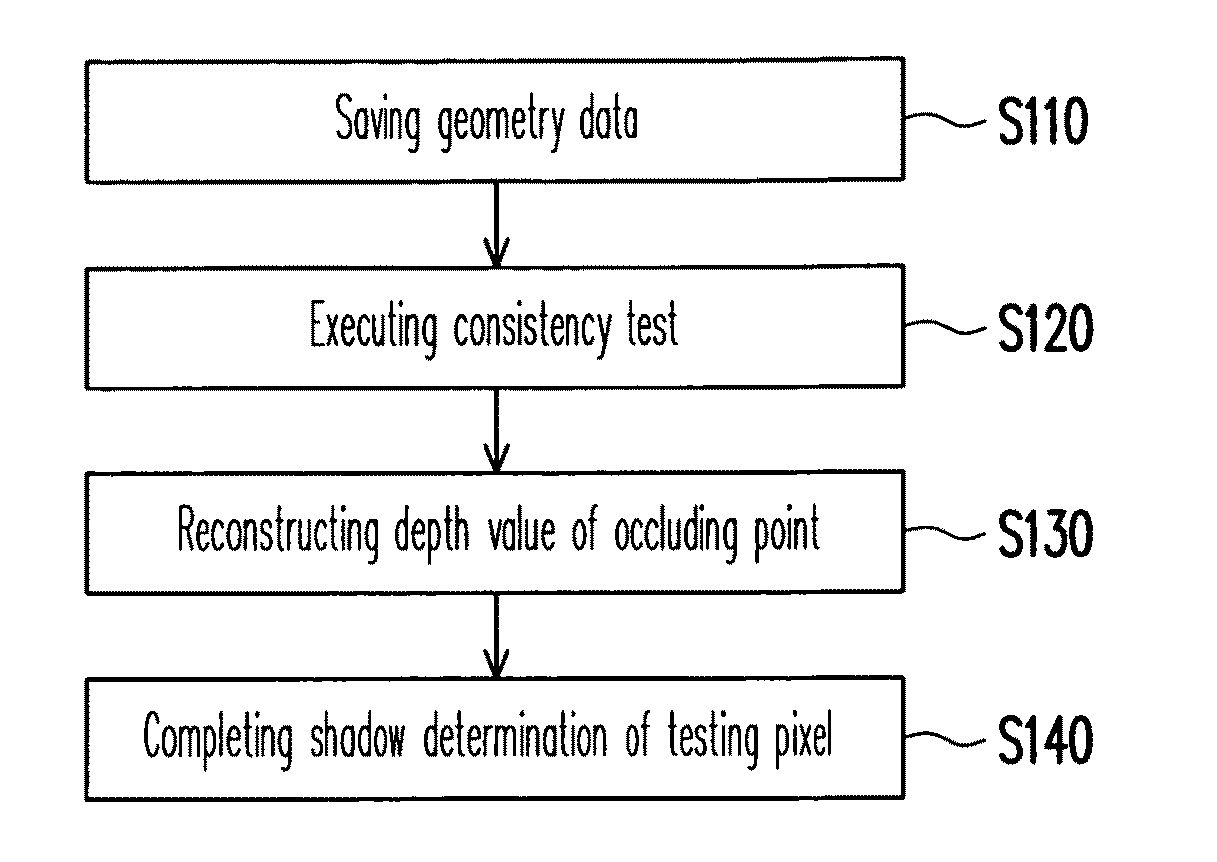
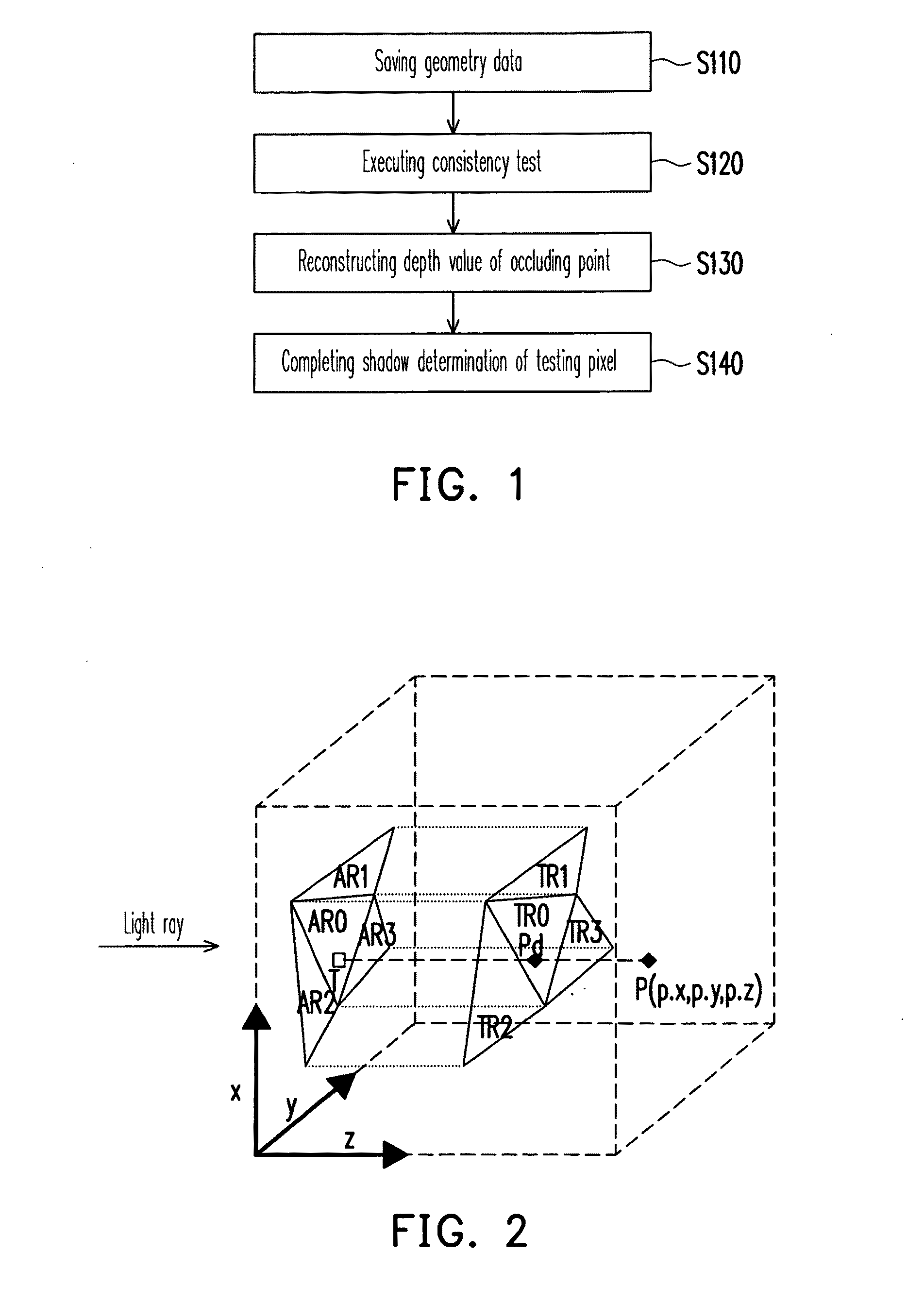
  • Reconstructable geometry shadow mapping method
  • Reconstructable geometry shadow mapping method
  • Reconstructable geometry shadow mapping method

Examples


Embodiment Construction

[0027]Reference will now be made in detail to the present preferred embodiments of the invention, examples of which are illustrated in the accompanying drawings. Wherever possible, the same reference numbers are used in the drawings and the description to refer to the same or like parts.

[0028]Those of ordinary skill in the art may comply with the present invention by referring to the embodiments to be illustrated herebelow. However, it should be noted that the embodiments may also be applied in form of a computer program saved in a computer readable storage medium so as to allow a computer to execute the reconstructable geometry mapping method.

[0029]FIG. 1 is a flow chart illustrating a reconstructable geometry shadow mapping (RGSM) method according to an embodiment of the present invention. The RGSM method can be used to process a plurality of light sources. However, for simplicity and convenience of illustration, only one light source is exemplified in the current embodiment in de...


PUM


Abstract

A reconstructable geometry mapping method is provided. The reconstructable geometry mapping method includes: extracting geometry information of a plurality of occluding geometry shapes of an object's front-face with respect to a light source's point of view; performing a consistency test on a testing pixel so as to determine an occluding geometry shape corresponding to the testing pixel from the object's front-face among the plurality of occluding geometry shapes, in which the occluding geometry shape includes an occluding point, and the testing pixel overlaps with the occluding point when viewing from the light's point of view; reconstructing a depth value of an occluding point corresponding to the testing pixel; and performing a shadow determination of the testing pixel.

Description

CROSS-REFERENCE TO RELATED APPLICATION[0001]This application claims the priority benefit of U.S.A. provisional application Ser. No. 60 / 982,727, filed on Oct. 26, 2007, all disclosures are incorporated therewith. This application also claims the priority of Taiwan application serial no. 97118693, filed May 21, 2008. All disclosure of the Taiwan application is incorporated herein by reference.BACKGROUND OF THE INVENTION[0002]1. Field of the Invention[0003]The present invention generally relates to a graphic processing technology, and more particularly, to a reconstructable geometry shadow mapping method.[0004]2. Description of Related Art[0005]Shadow mapping and shadow volume are two popular real time shadowing technologies for computer graphics. Shadow volume is proposed by Frank Crow in 1977, in which the geometry is employed for calculating the 3-dimensional (3-D) shape of a region occluded from a light source. The algorithm utilizes a stencil buffer to calculate whether a pixel is...

Claims


Application Information

Patent Timeline
Patent Type & Authority Applications(United States)
IPC IPC(8): G06T15/60
CPCG06T15/60
Inventor DAI, QINGHUAYANG, BAOGUANG
Owner VIA TECH INC
Learn More