Image forming apparatus

a technology of image forming apparatus and forming plate, which is applied in the direction of typewriters, instruments, data recording, etc., can solve the problems of long time required for forming images, damage to the recorded surface of the medium, and printers having to be provided separately, so as to reduce the differences in tonal shading and eliminate problems. , the effect of reducing the density

Inactive Publication Date: 2009-04-30
CITIZEN WATCH CO LTD
View PDF6 Cites 6 Cited by
  • Summary
  • Abstract
  • Description
  • Claims
  • Application Information

AI Technical Summary

Benefits of technology

[0021]The present invention firstly eliminates the occurrence of incomplete portions in solid image areas and of missing parts and overlapping parts in printed lines by printing so as to cause partial overlapping between pixels which are mutually adjacent in the circumferential direction of rotation, and furthermore eliminates the occurrence of tonal shading in the radial direction by adjusting the printing density of the respective pixels.
[0056]Moreover, according to the present invention, it is possible to eliminate positional deviation of the image data which occurs when printing onto a disk-shaped recording medium using image data having pixel tone values which are specified for integer coordinates points on a perpendicular coordinates system.

Problems solved by technology

When information is written directly to the surface of the disk-shaped medium in this way, since a writing tool is used then there is a risk of damaging the recorded surface of the medium, and if the information is printed onto a paper label using a printer, then there is a problem in that a printer has to be provided separately.
A printer such as that described in the patent reference mentioned above is problematic in that since an image is formed on the surface of the optical disk by progressive dot scanning which prints successively in a spiral shape or concentric shape, one pixel at a time, while moving the optical disk and the optical pick-up relatively over the surface of the optical disk, then a long time is required in order to form an image.
On the other hand, if a recording head is disposed in a radiating fashion from the central portion of a disk-shaped recording medium and line-shaped recording is performed successively in synchronism with the rotation of the recording medium, then positional deviation will occur in the points which are printed on the disk surface if printing is performed by using the coordinates points on the perpendicular coordinates system directly without any modification, and hence there is a risk that the printing quality will decline.
Furthermore, if printing is carried out onto the surface of a rotating disk by using a print head in which printing elements are arranged in the outer circumferential direction from the center of rotation, then there are problems in that tonal shading occurs in the radial direction, incomplete portions arise in solid filled image areas, and missing lines or overlaps occur in the printed lines.
However, in image data processing for thinning data in this way, for instance, it is only possible to thin out a centrally placed dot if there is overlap between three mutually adjacent dots.
Therefore, it is not necessarily the case that image data can be thinned on the basis of the image data to be printed, and hence there is a problem in that the overlap between dots on the inner circumferential side cannot be eliminated completely.

Method used


Image

  • Image forming apparatus
  • Image forming apparatus
  • Image forming apparatus

Examples


Embodiment Construction

[0124]Firstly, an embodiment of the image forming apparatus according to the present invention will be described.

[0125]Below, the image forming apparatus according to the present invention is described in detail with reference to the drawings.

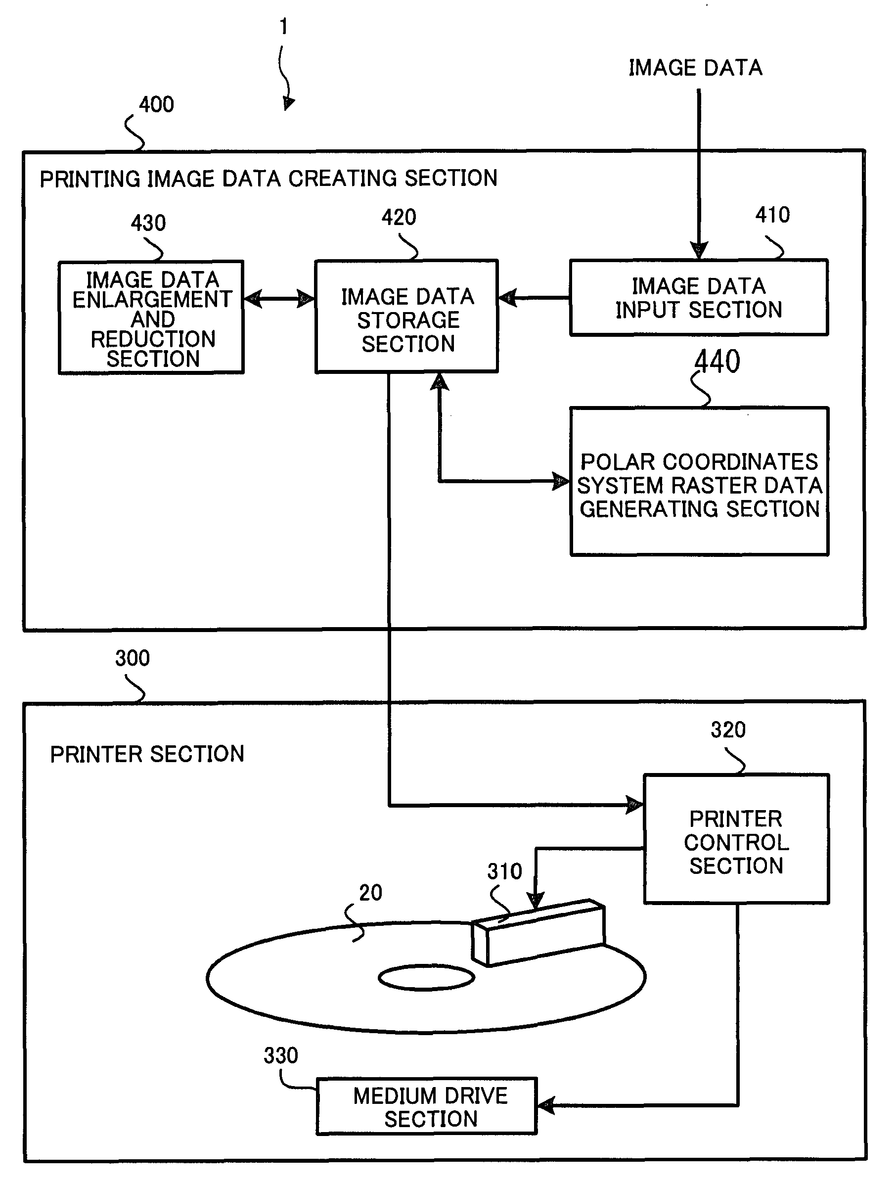
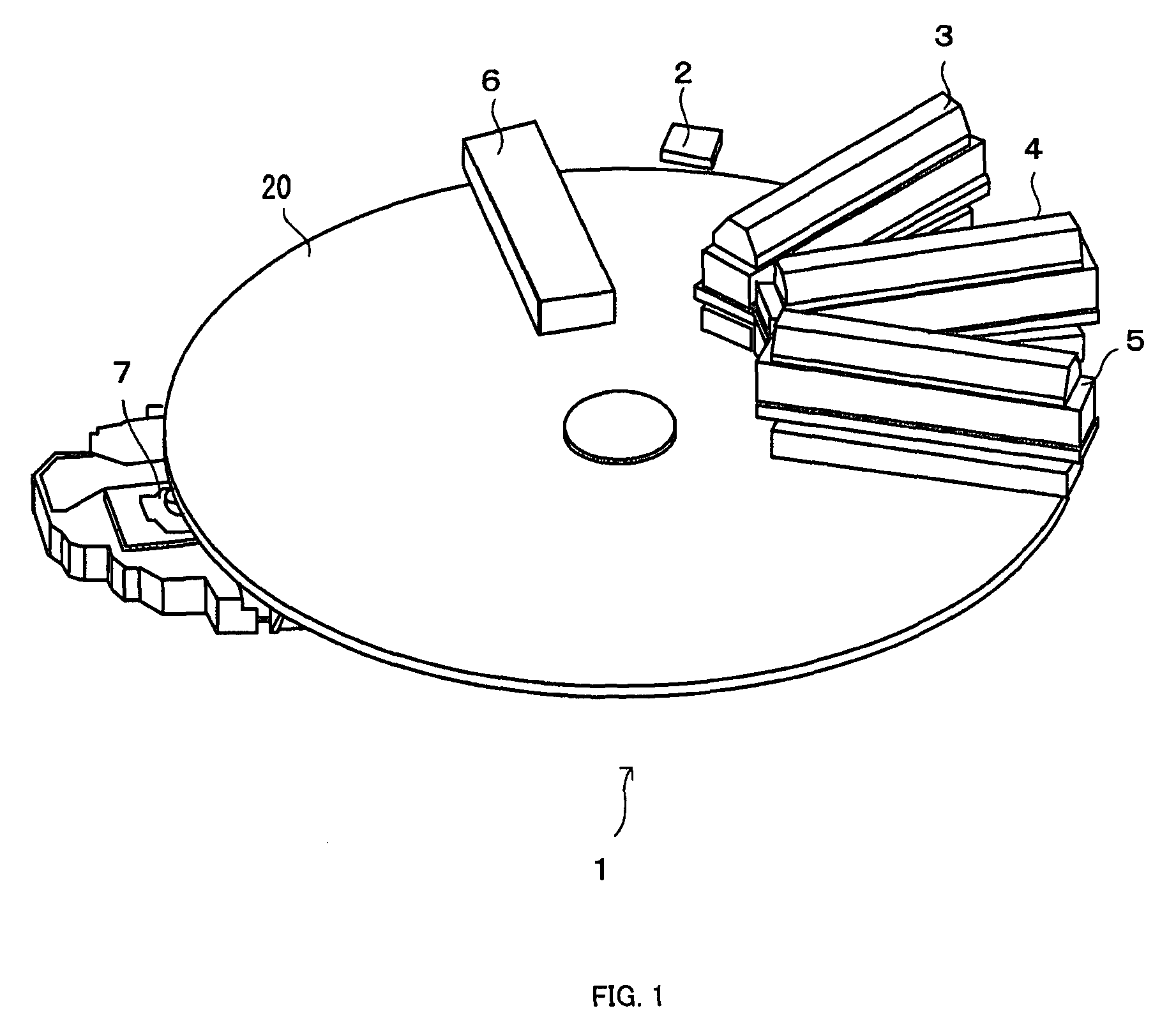
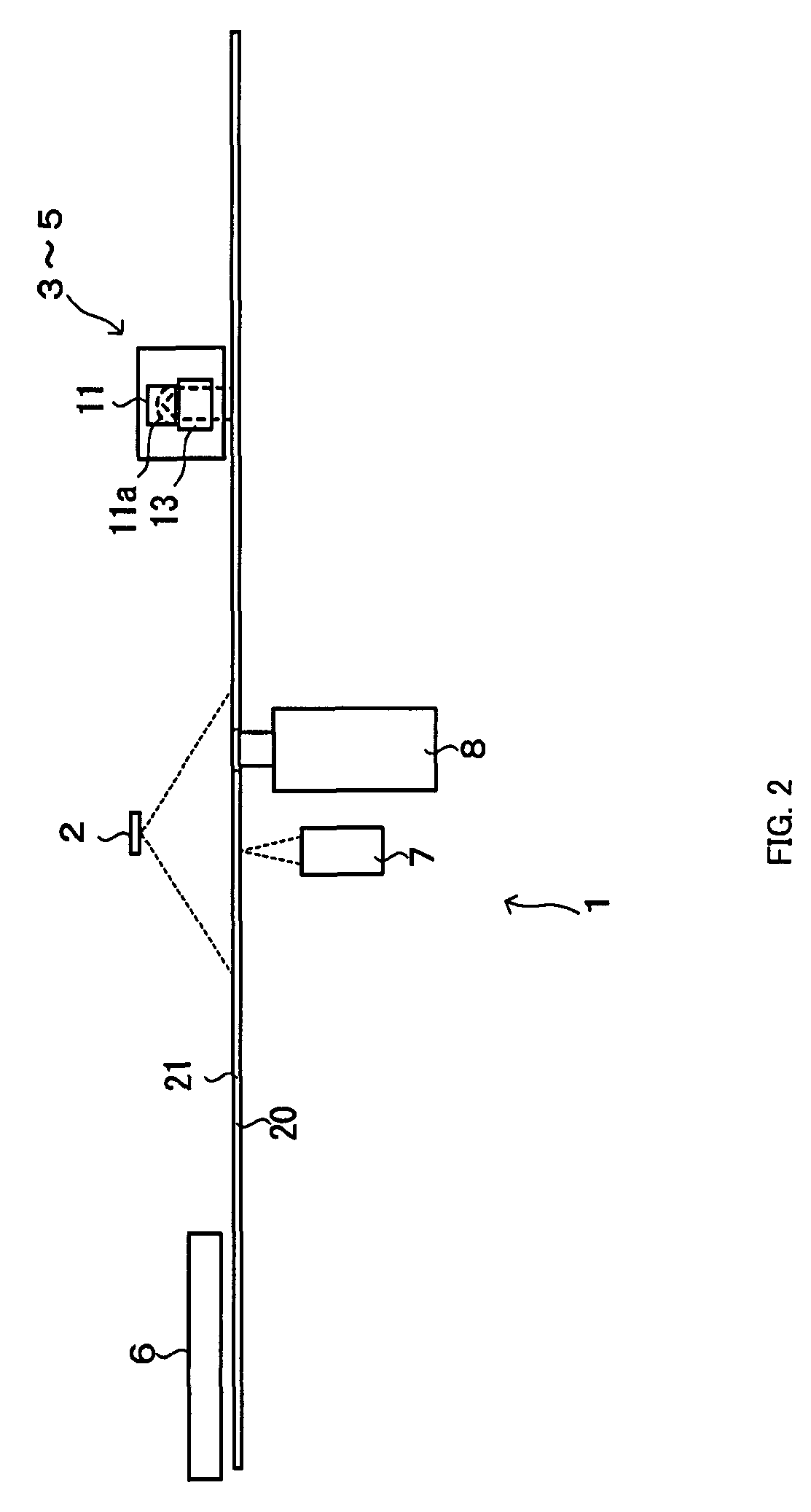
[0126]Firstly, the general composition of the image forming apparatus of the present invention is described with reference to the general perspective diagram in FIG. 1 and the general cross-sectional diagram in FIG. 2.

[0127]In the general compositional diagram of the image forming apparatus shown in FIG. 1, the image forming apparatus 1 comprises a mechanism (not illustrated) for driving a medium 20 in rotation and a pick up 7 which optically records information onto an information recording surface of the medium 20; the pick up 7 carries out recording by irradiating laser light onto the information recording surface of the medium 20 on the basis of the data to be recorded. The data to be recorded may be data of various types, such as image dat...


PUM


Abstract

Problems, which occur when printing is performed on the surface of a rotating disk using by using a print head arranged in the outer circumferential direction from the center of rotation, are resolved. Light emitting sections performs exposure in synchronism with rotational driving for rotating a medium, and pixels which are adjacent in the circumferential direction of rotation are exposed in a partially superimposed fashion by making the amount of movement in the circumferential direction along which the outermost circumference of the medium moves between exposures smaller than the width in the circumferential direction of the pixels formed by exposure. In a plurality of light emitting sections provided in an optical unit, the quantity of light for exposing a pixel on the inner circumferential side in the radial direction is set to be smaller than the quantity of light for exposing a pixel on the outer circumferential side in the radial direction for the respective exposure positions for the medium. Therefore, difference in the tonal shading caused by superposition is reduced by lowering the density created by each exposure in respect of the pixels on the inner circumferential side in the radial direction where there is a large overlap between exposures.

Description

TECHNICAL FIELD[0001]The present invention relates to an image forming apparatus and more particularly to an image forming apparatus which forms images on a disk-shaped medium.BACKGROUND[0002]Disk-shaped media such as CD, CD-R, CD-RW, DVD, DVD-RAM, and the like, are known as recording media for recording electronic data such as images, videos, sound, documents and the like. When writing and recording various types of data on these disk-shaped media, there are cases where information such as a title relating to the recorded contents is inscribed on the surface of the disk-shaped medium in order that the contents recorded on the disk-shaped medium can be identified visually.[0003]In this case, generally, the information is written on the surface of the disk-shaped medium using a writing tool, but there are also cases where recording information is printed on a separately prepared paper label by a printer and then the label is attached to the surface of the disk-shaped medium.[0004]Whe...

Claims


Application Information

Patent Timeline
Patent Type & Authority Applications(United States)
IPC IPC(8): B41J2/435
CPCB41J2/45G11B23/40B41J3/4071
Inventor HORI, FUMIHISAOSAKAMA, CHIKASHIMURAYAMA, HIROYUKICHIDA, MAKOTO
Owner CITIZEN WATCH CO LTD
Why Eureka
Try Eureka