Method and apparatus for rejecting the second harmonic current in an active converter with an unbalanced AC line voltage source

a technology of unbalanced ac line voltage and active converter, which is applied in the direction of dc circuit to reduce harmonics/ripples, emergency protective circuit arrangements, conversion with intermediate conversion to dc, etc., can solve the problems of significant harmonic distortion, unusable converter, hardware adds expense to the overall system, etc., and achieves the effect of reducing the second harmoni

Active Publication Date: 2008-04-08
ROCKWELL AUTOMATION TECH
View PDF2 Cites 33 Cited by
  • Summary
  • Abstract
  • Description
  • Claims
  • Application Information

AI Technical Summary

Benefits of technology

[0012]It has been recognized that, given certain reasonable assumptions, equations can be formulated to identify the amplitudes of supply line voltages from RMS line-to-line voltages which can in turn be used to identify supply line voltages that would result from active conversion of the unbalanced voltages. Once the second harmonic components of the supply line voltages that would result from normal active conversion have been identified, the identified second harmonic components can be used to modify converter command or control signals so that the second harmonics that are actually generated are substantially minimized. When the second harmonics in the supply line voltages are minimized, the converter currents are more balanced and a conversion rate (i.e., converter capacity) can be increased. In addition, when the supply line second harmonics are minimized, DC bus ripple is substantially reduced.
[0013]The compensation step can be performed in either a two phase synchronous dq frame of reference or in a three phase stationary frame of reference. The calculations in the two phase reference frame are more complex than in the three phase reference frame and therefore, all other things being equal, it may be advantageous to perform the process in a three phase reference frame. However, many existing controllers are programmed to operate in the two phase reference frame and therefore, in many cases, two phase compensation may be advantageous.
[0026]The invention also contemplates a method for use with a controller and a converter wherein the controller receives a reference voltage and generates first, second and third phase control voltages as a function of the reference voltage, the converter receiving the first, second and third phase control voltages and first, second and third phase line voltages and converting the line voltages to a DC voltage across positive and negative DC buses as a function of the control voltages where the line voltages may be unbalanced, the method for substantially reducing the second harmonics in the first, second and third phase line currents caused by drawing current from the lines when the line voltages are unbalanced, the method comprising the steps of identifying first, second and third RMS line-to-line voltages, using the RMS line-to-line voltages to identify peak phase voltage values, mathematically combining the peak phase voltage values and at least a derivative of the reference voltage to generate the first, second and third phase command voltages; and using the first, second and third phase command voltages to control the converter.
[0027]At least some embodiments of the invention include a method for use with a controller and a converter where the controller actively controls the converter to convert three phase voltages on three supply lines to a DC voltage across positive and negative DC buses, the method comprising the steps of identifying unbalance in the peak amplitudes of the three phase supply line voltages and using the unbalance to alter control of the converter to substantially eliminate generation of second harmonics on the supply lines due to active converter control.

Problems solved by technology

Unfortunately, six-pulse converters have been known to generate high levels of harmonics (e.g., fifth, seventh, third, eleventh, thirteenth, etc.) on linked supply lines which render these converters unusable under certain circumstances or useable only if other conditioning hardware is used therewith.
Here, the other conditioning hardware adds expense to the overall system.
Unfortunately, when supply line voltages are unbalanced, it has been observed that 12 and 18 pulse conversion can result in significant harmonic distortion.
Unfortunately, it has been observed that when supply line voltages are unbalanced, active conversion can generate second harmonics that exceed tolerable levels.
In addition, when the supply line voltages are unbalanced, active conversion often results in unbalanced current draw.
In other words, once the current through one phase reaches the rated current level, the converter capacity must be limited to protect that phase despite the fact that the other two phases may have current levels far below the rated level.
Moreover, it has been observed that under certain circumstances unbalanced supply line voltage causes increased voltage ripple on the DC bus (i.e., the link between the converter and the inverter in an AC-DC-AC conversion topology) which can cause increased heating and can shorten the useful life of conversion hardware components as well s the useful life of inverter components linked to the DC bus.

Method used


Image

  • Method and apparatus for rejecting the second harmonic current in an active converter with an unbalanced AC line voltage source
  • Method and apparatus for rejecting the second harmonic current in an active converter with an unbalanced AC line voltage source
  • Method and apparatus for rejecting the second harmonic current in an active converter with an unbalanced AC line voltage source

Examples


first embodiment

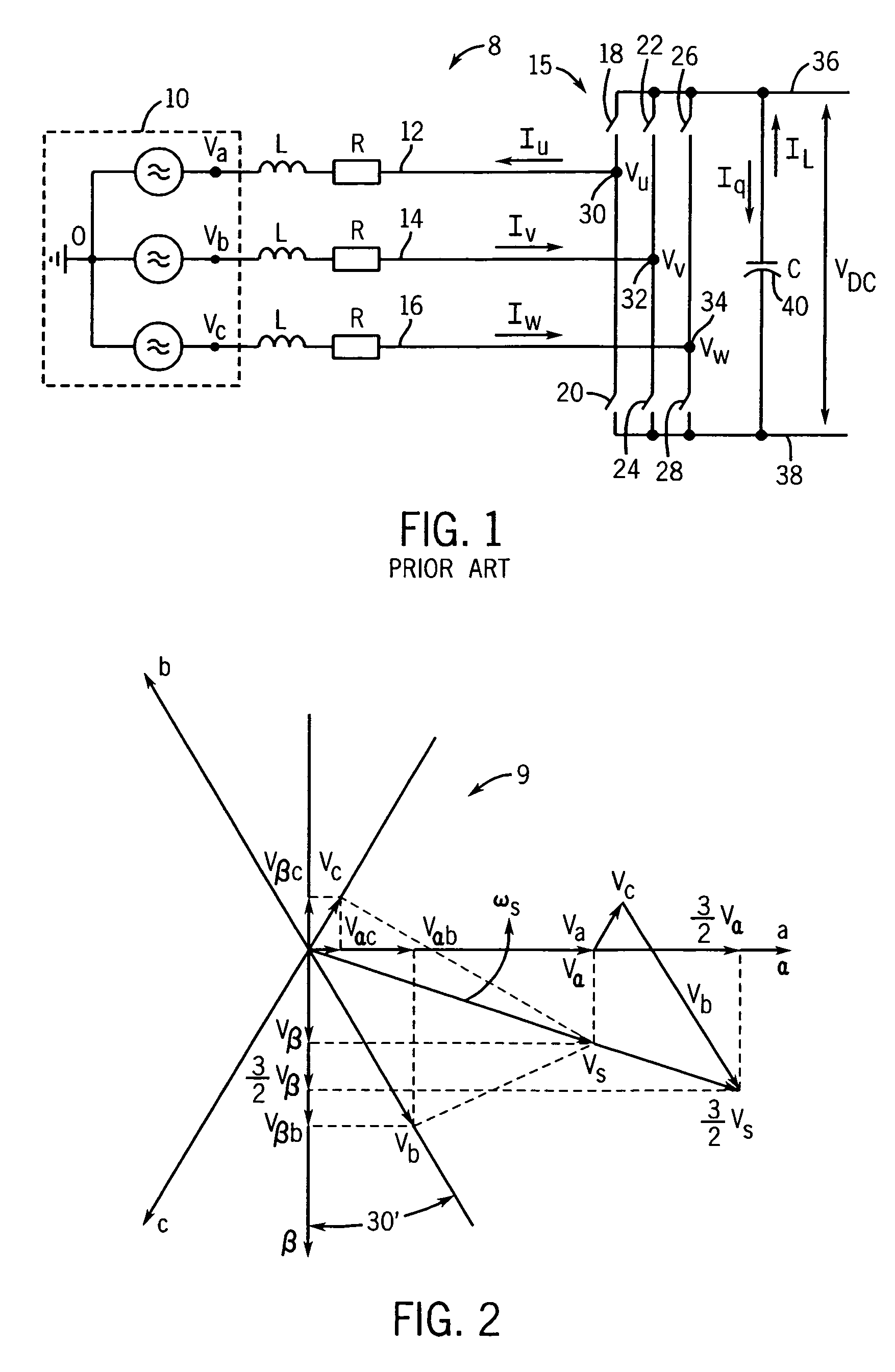
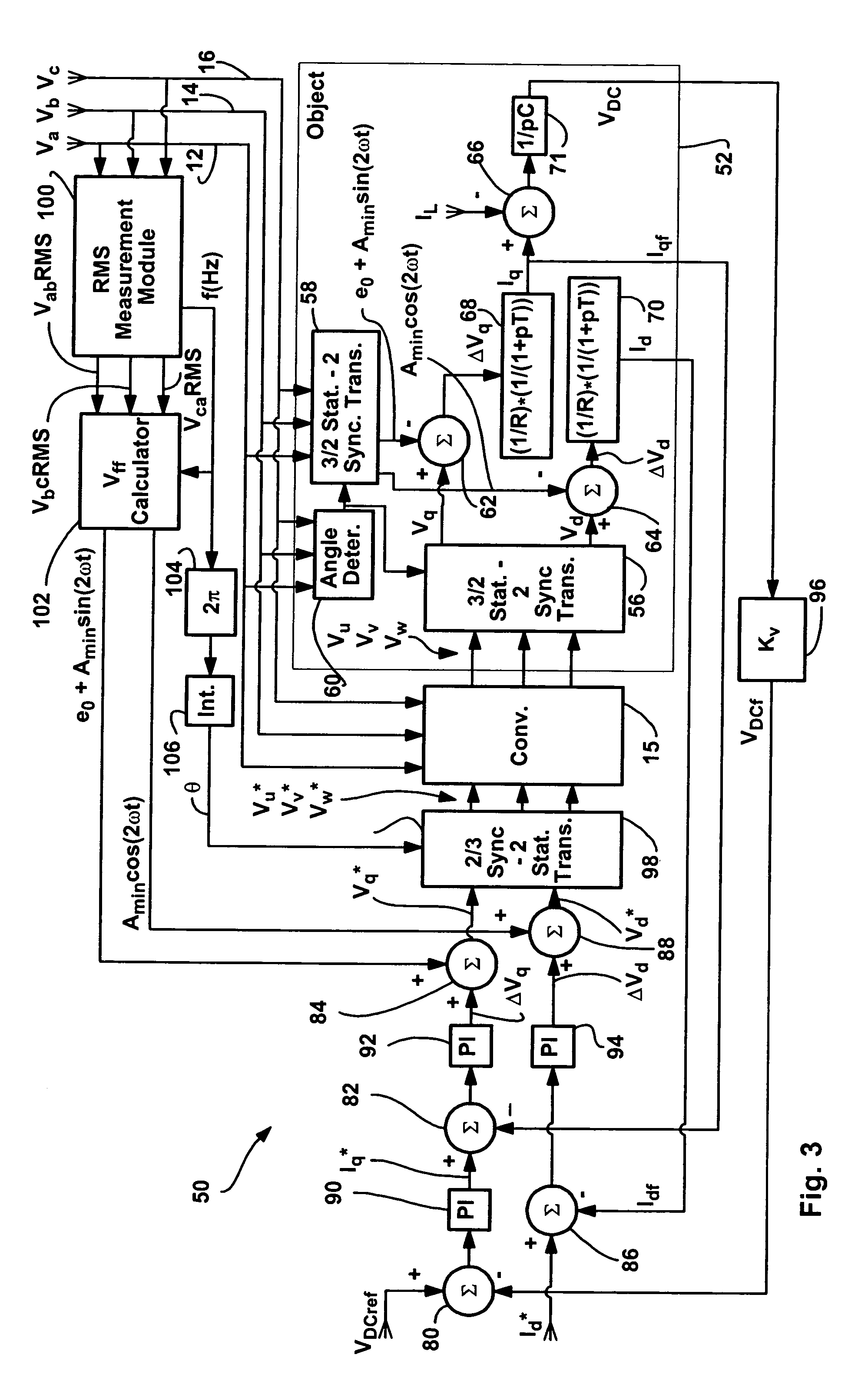
[0088]Referring now to FIG. 3, an exemplary controller 50 linked to a converter 15 is illustrated. Controller 50 receives a DC bus voltage reference value VDCref and controls converter 15 so that converter 15 generates a DC bus voltage VDC (see again FIG. 1) that is equal to the reference voltage VDCref. In this regard, as illustrated in FIGS. 1 and 3, three phase supply line voltages Va, Vb and Vc are provided to converter 15 and converter 15 is controlled in a manner consistent with command voltage values V*u, V*v l and V*w to cause the DC bus voltage to track the reference voltage VDCref.

[0089]In addition to the controller 50 and converter 15, a synchronous two phase dq reference frame object model 52 is illustrated for discussion purposes to simulate converter operation when unbalanced supply line voltages occur on lines 12, 14 and 16. Object model 52 includes an angle θ determiner 60, two stationary three-phase to synchronous two phase transformers 56 and 58, three summers 62, ...

second embodiment

[0102]While most control configurations operate in the synchronous two-phase dq reference frame, it is possible to configure a controller that operates in the three phase stationary frame of reference. In this case, Equations 1 through 3 and Equations 64 through 66 can be used to identify three phase feed forward voltages to substantially eliminate the second harmonic components in the line voltages and to reduce DC bus ripple.

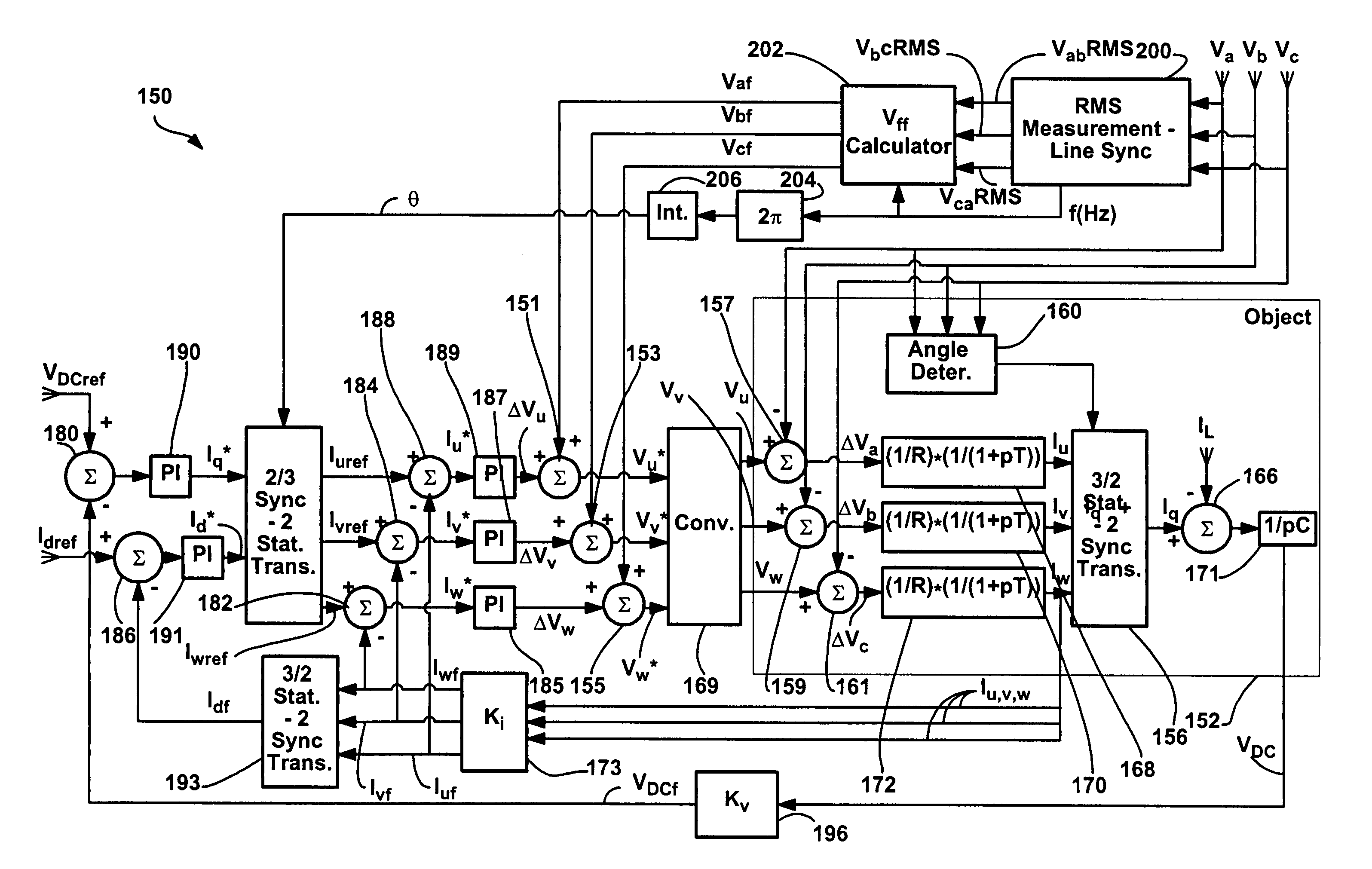
[0103]Referring now to FIG. 5, a schematic diagram similar to the diagram provided in FIG. 3 as illustrated that includes a three phase object model 152 to illustrate the effects of active conversion with unbalanced supply line voltages, a three phase controller 150 and a converter 169. Converter 169 receives the supply line voltages Va, Vb and Vc and generates voltage values Vu, Vv and Vw as a function of command voltages V*u, V*v and V*w.

[0104]Object model 152 includes four summers 157, 159, 161 and 166, an angle determiner 160, four scalar modules 168, 170,...


PUM


Abstract

A method and apparatus for altering converter control as a function of the degree of unbalance in supply line voltages to substantially eliminate second harmonics on the supply lines caused by active control of the converter including identifying supply line peak amplitude values and using the peak values to identify potential second harmonics and then altering command values as a function of the potential second harmonic components.

Description

CROSS-REFERENCE TO RELATED APPLICATIONS[0001]Not applicable.STATEMENT REGARDING FEDERALLY SPONSORED RESEARCH OR DEVELOPMENT[0002]Not applicable.BACKGROUND OF THE INVENTION[0003]Power consuming clients that link to a utility power grid and draw power therefrom have to limit the amount of disturbance they cause at the grid coupling point so that other customers linked to the grid can rely on a power at the coupling point that has at least certain characteristics (e.g., a limited amount of harmonics, a limited amount of unbalance, etc.). To this end a series of regulations (e.g., IEEE 519) have been adopted that specify grid linkage / power usage requirements.[0004]AC power delivered to coupling points via grid lines (i.e., supply lines) is usually not in a condition that can be used by end users and therefore the power at the coupling point must be converted so as to have characteristics required by the end users. For instance, grid AC power is often converted from AC to DC via a rectif...

Claims


Application Information

Patent Timeline
Patent Type & Authority Patents(United States)
IPC IPC(8): H02M1/12
CPCH02M1/12H02M1/4233Y02B70/126Y02B70/10
Inventor ROYAK, SEMYONBREITZMANN, ROBERT JOHN
Owner ROCKWELL AUTOMATION TECH
Why Eureka
Try Eureka