Method for producing porous laminate and porous laminate

a technology of porous film and porous laminate, which is applied in the direction of packaging, synthetic resin layered products, chemical production, etc., can solve the problems of large amount of organic solvent, unpreferable for environment, and inability to produce porous film, so as to achieve wide production conditions, reduce environmental load, and reduce environmental load

Active Publication Date: 2009-07-16
MITSUBISHI CHEM CORP
View PDF8 Cites 32 Cited by
  • Summary
  • Abstract
  • Description
  • Claims
  • Application Information

AI Technical Summary

Benefits of technology

[0189]The method of the present invention for producing the porous laminate is thereby capable of securing the interconnectability in the thickness direction of the porous laminate by eliminating the generation of the skin layer in utilizing the subcritical fluid or the supercritical fluid. The elimination of the generation of the skin layer is a problem to be solved in utilizing the subcritical fluid or the supercritical fluid.
[0190]The subcritical fluid or the supercritical fluid is used to allow the interlayer to be porous, and a large amount of the organic solvent is not used. Therefore it is possible to apply a smaller amount of load to environment. By using a non-toxic inactive gas such as carbon dioxide or nitrogen as the subcritical fluid or the supercritical fluid, it is possible to apply a much smaller amount of load to the environment. The method for producing the porous laminate of the present invention has an advantage that the producing condition is wide and thus producing steps can be easily managed.
[0191]In a method of making a laminate porous by removing a plasticizer or a solvent, there is a possibility that the plasticizer or the solvent remains without being removed. In the present invention, because the subcritical fluid or the supercritical fluid is utilized in allowing the interlayer to be porous, the above-described problem that the plasticizer or the solvent remains in the interlayer does not occur but it is possible to produce the porous laminate having a small amount of impurities. In addition, the method of the present invention for producing the porous laminate is wide in its producing condition and is hence capable of easily managing the producing steps.
[0192]By containing the filler in both outer layers of the porous laminate of the present invention, the porous laminate is allowed to have a proper degree of irregularities on the surface thereof. Thereby the porous laminate of the present invention can be preferably used as a porous sheet or film, for example, a separator for a battery demanded to be rough on its surface to some extent. In the separator for the battery, the sliding performance of the porous laminate is improved and handling performance is preferable in the process of winding it.
[0193]In the case of a porous film for the battery separator conventionally provided, the maximum height (Rmax) of the surface of the porous film is normally 1 to 2 μm when it is measured by the method described in JIS-B-0610. In addition, in applying a known film-roughening technique to the porous film, for example, in applying the known technique of attaching micro-particles or short fibers to the surface of the porous film, there occurs a problem that essential property requirements for the battery separator such as the strength of the surface thereof, the shut-down characteristic, and the like are damaged.
[0194]In comparison with the conventional porous film, it is possible to set the maximum height (Rmax) of the surface of the porous laminate of the present invention to not less than 2 μm without damaging the essential property requirements for the battery separator such as the strength of the surface thereof, the shut-down characteristic, and the like. Therefore the porous laminate of the present invention is capable of contributing to an increase of the capacity of a battery and the improvement of the handling performance in the process of winding it.

Problems solved by technology

In the above-described method, as described at the paragraph number of the specification, because the solvent is extracted by being cleaned with the organic solvent for cleaning use, a large amount of the organic solvent is necessary, which is unpreferable for environment.
Therefore it is unpreferable to produce the porous film by using the above-described method when considering a process management for producing it in the industrial scale.
Therefore it is impossible to form a porous laminate having micro-pores interconnected with each other in the thickness direction thereof.

Method used


Image

  • Method for producing porous laminate and porous laminate
  • Method for producing porous laminate and porous laminate
  • Method for producing porous laminate and porous laminate

Examples


example 1

[0267]As preparation of a resin composition composing both outer layers, 100 parts by mass of high-density polyethylene and 100 parts by mass of barium sulfate were blended with each other to form a compound. In the example 1, the compound did not contain a plasticizer.

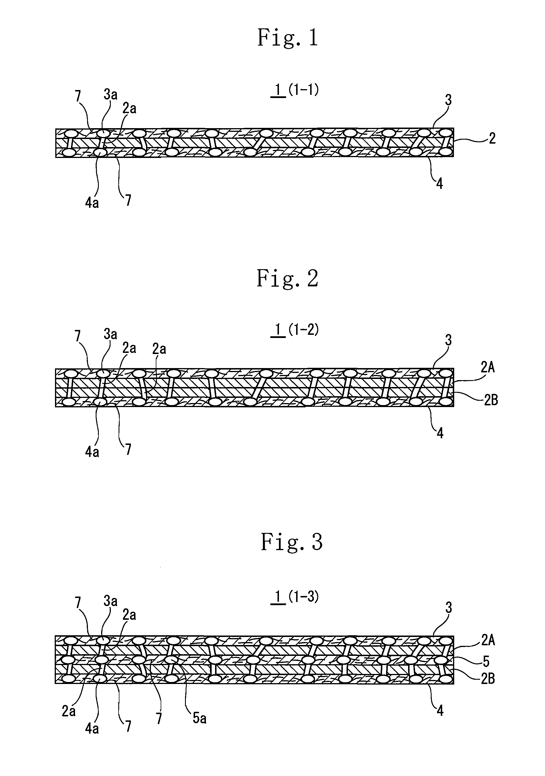
[0268]The compound was used as both outer layers, and a thermoplastic resin composition composed of polypropylene containing ethylene-propylene rubber was used as the polypropylene resin composition composing the interlayer. The ratio among the outer layer 1, the outer layer 2 and the interlayer was adjusted to the outer layer 1 / the interlayer / the outer layer 2=25 / 50 / 25. By using a multi-layer forming T-die, both resin compositions were molded at a temperature of 200° C. to obtain a laminate composed of three layers made of two kinds of the resin compositions.

[0269]After the obtained laminate was put in a pressure container, carbon dioxide which is an inactive gas was enclosed in the pressure container at a normal tem...

examples 2 through 5

[0271]The porous laminates of the examples 2 through 5 were obtained in a manner similar to that of example 1 except that the resin composition composing both outer layers contained a plasticizer consisting of hardened caster oil and that the stretching condition was altered, as shown in table 1.

examples 6 , 7

Examples 6, 7

[0272]The porous laminates of the examples 6, 7 were obtained in a manner similar to that of the examples 2 through 5 except that the resin composition composing both outer layers was composed of a polypropylene homopolymer and an ethylene-propylene rubber.

TABLE 1OUTERMOST LAYER 1INTERLAYEROUTERMOST LAYER 2THERMO-OTHERCOMPO-POLYPROPYLENETHERMO-OTHERCOMPO-PLASTICCOMPO-SITIONRESINPLASTICCOMPO-SITIONRESINFILLERNENTSRATIOCOMPOSITIONRESINFILLERNENTSRATIOEXAMPLE 17000FPB55NONE50 / 50 / 0ZELAS50137000FPB55NONE50 / 50 / 0EXAMPLE 27000FPB55HCOP47 / 50 / 3ZELAS50137000FPB55HCOP47 / 50 / 3EXAMPLE 3HY430P30NCHCOP67 / 30 / 3ZELAS5013HY430P30NCHCOP67 / 30 / 3EXAMPLE 47000FPB54HCOP37 / 60 / 3ZELAS50137000FPB54HCOP37 / 60 / 3EXAMPLE 57000FPB55HCOP47 / 50 / 3ZELAS50137000FPB54HCOP37 / 60 / 3EXAMPLE 67000FPB55HCOP47 / 50 / 3F104A / T310V50 / 507000FPB55HCOP47 / 50 / 3EXAMPLE 77000FPB55HCOP47 / 50 / 3F104A / T310V25 / 757000FPB55HCOP47 / 50 / 3COMPARISONFILM OF EXAMPLE 1 OF JAPANESE PATENT APPLICATION LAID-OPEN NO. 05-025305EXAMPLE 1COMPARISONFILM OF ...


PUM

PropertyMeasurementUnit
particle diameteraaaaaaaaaa
heat shrinkage percentageaaaaaaaaaa
heightaaaaaaaaaa

Abstract

A process for producing a porous laminate having many micropores interconnected in the thickness direction, which comprises: a step in which a laminate is produced which comprises at least three layers comprising an interlayer made of a thermoplastic resin having a hard segment and a soft segment and two nonporous outer layers made of a filler-containing resin and located as outer layers respectively on both sides of the interlayer; a step in which the laminate obtained is impregnated with a supercritical or subcritical fluid and this state is relieved to vaporize the fluid and thereby make the interlayer porous; and a step in which the two nonporous outer layers located respectively on both sides are made porous by stretching.

Description

TECHNICAL FIELD[0001]The present invention relates to a method for producing a porous laminate and the porous laminate obtained by using the producing method. The porous laminate is preferably utilized as packing articles, sanitary articles, livestock articles, agricultural articles, building articles, medical appliances, a separation film, a light diffusion plate, a reflection sheet, and a separator for a battery.BACKGROUND ART[0002]A polymeric porous film or sheet having a large number of micro-pores is utilized in various fields as separation films for use in the production of ultra-pure water, the formation of chemicals, water treatment; waterproof moisture-permeable films for use in cloths, sanitary materials, and the like; and a separator for a battery.[0003]As this kind of techniques for forming a large number of interconnected micro-pores in high polymers, various techniques described below are proposed.[0004]For example, proposed in Japanese Patent Application Laid-Open No....

Claims


Application Information

Patent Timeline
Patent Type & Authority Applications(United States)
IPC IPC(8): H01M2/16B29C44/04B32B3/26B29C67/20B32B5/18B32B5/32B32B27/32C08J9/00C08J9/12H01M6/16H01M10/05H01M50/417H01M50/491
CPCB29C44/06Y10T428/24504B29C44/348B32B5/18B32B5/32B32B27/08B32B27/20C08J9/122C08J2201/032C08J2203/08C08J2205/05C08J2323/12H01M2/1653B32B5/14B32B5/20B32B25/08B32B27/18B32B27/205B32B27/22B32B27/302B32B27/304B32B27/306B32B27/308B32B27/32B32B27/34B32B27/36B32B27/365B32B38/0032B32B3/26B32B2250/40B32B2264/102B32B2264/104B32B2266/0228B32B2266/025B32B2266/0257B32B2266/0264B32B2266/0292B32B2270/00B32B2274/00B32B2307/102B32B2307/304B32B2307/306B32B2307/538B32B2307/72B32B2307/724B32B2307/734B32B2410/00B32B2419/06B32B2437/00B32B2439/70B32B2457/10B32B2535/00B32B2551/00B32B2555/00B32B2555/02B32B2607/02B29C44/3453Y02P20/54Y02E60/10H01M50/417H01M50/491
Inventor USAMI, YASUSHINEMOTO, TOMOYUKITAKAGI, JUNTESHIMA, SATOSHI
Owner MITSUBISHI CHEM CORP
Why Eureka
Try Eureka