Percutaneous Fixator and Method of Insertion

a technology of percutaneous fixation and insertion method, which is applied in the field of skeletal fixation, can solve the problems of trauma associated with surgical access to the proximal portion of the tibia, and achieve the effect of reducing the risk of fractur

Active Publication Date: 2009-04-30
COLE J DEAN
View PDF14 Cites 25 Cited by
  • Summary
  • Abstract
  • Description
  • Claims
  • Application Information

AI Technical Summary

Benefits of technology

[0008]The present invention also provides a technique to permit percutaneous fixator insertion utilizing image-guided surgical techniques. More specifically, an obturator and / or a protective sheath may be provided with a reference marker identifiable by an image-guided surgery system. Additionally, in a preferred aspect a guide wire is also fitted within an image-guided sensor to denote its location within the bone of interest. In this technique, the plate gripping tool may also include a reference marker such that when the plate is fixably attached to the gripping tool, the reference marker denotes the location and orientation of the plate as registered by the image-guided surgical computers. In this manner, a surgeon may specifically identify the orientation of the guide wire and surrounding protective sheath to determine the trajectory of implantation. This may be determined through sequential x-ray imaging or other imaging techniques or by utilizing pre-defined images stored within a computer aided image-guided surgery system. After determination of the proper trajectory, a cutting tool or broach may be advanced within the guide sleeve and preferably guided by the guide wire to define an aperture extending into the intramedullary canal within the bone of interest. The cutting tool may then be withdrawn. A fixation plate may be gripped by an insertion tool and advance within the guide sheath to the predetermined position within the patient. It will be understood that the use of image-guided reference markers on the insertion tool may assist the surgeon in determining the orientation within the patient and the proper location extending along the bone. Additionally, the image-guided reference markers may assist the surgeon when placing nails through the bone and through the apertures in the fixation plate.

Problems solved by technology

In this procedure, much of the trauma associated with the surgical access to the proximal portion of the tibia occurs in moving the patella laterally and posteriorly because it blocks access to the desired entry site.

Method used


Image

  • Percutaneous Fixator and Method of Insertion
  • Percutaneous Fixator and Method of Insertion
  • Percutaneous Fixator and Method of Insertion

Examples


Embodiment Construction

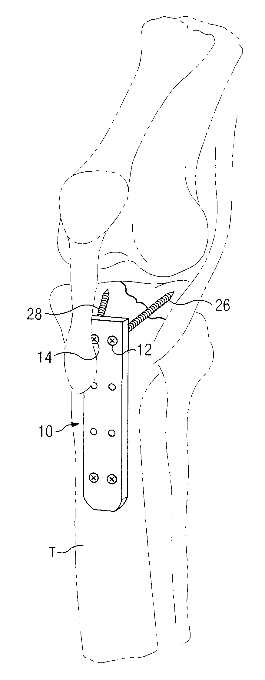
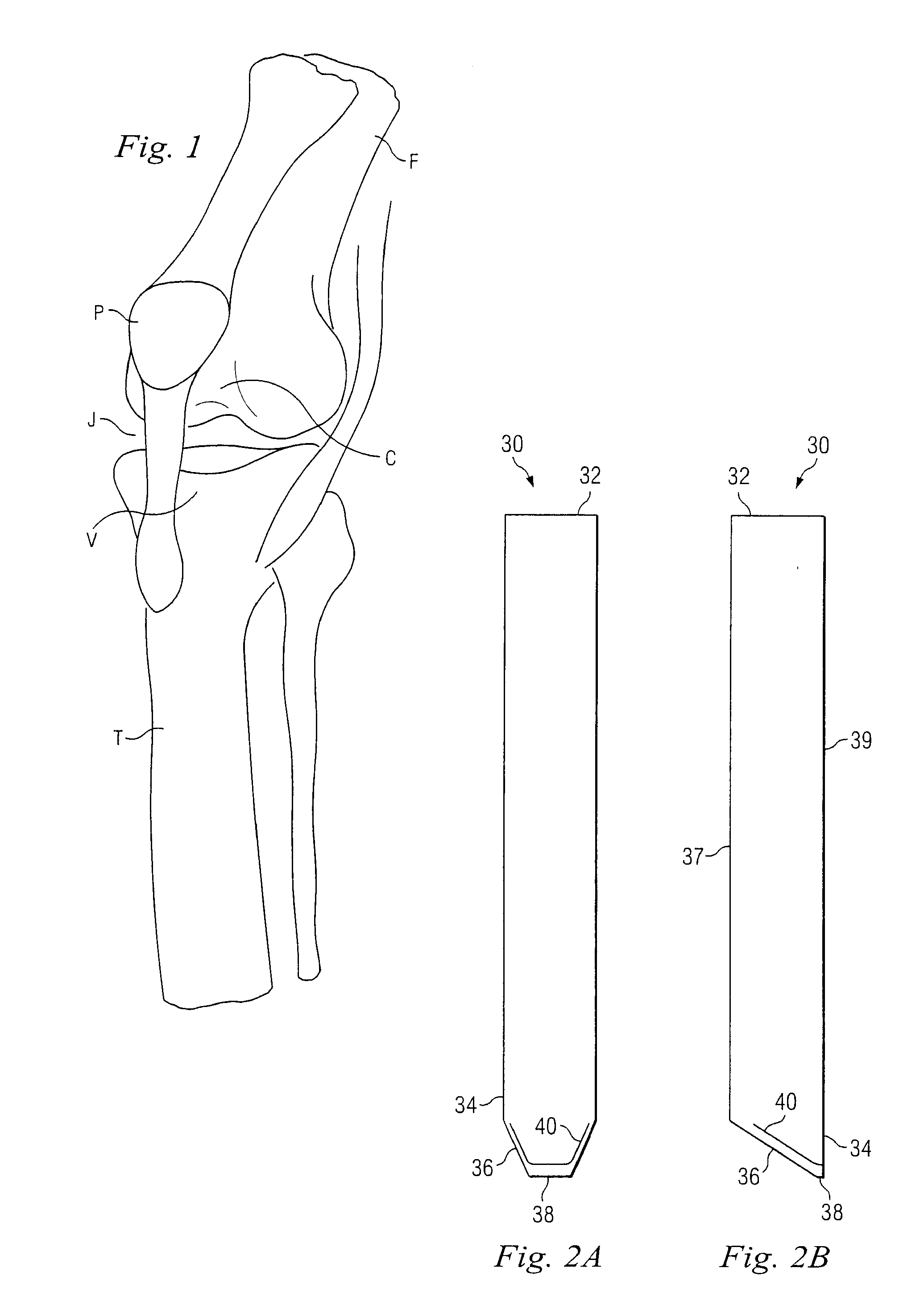
[0018]The present invention provides improved techniques, instruments and internal fixation devices permitting percutaneous fixation within the intramedullary canal of the long bone. In a preferred aspect, the instrument technique and fixation devices may be utilized for plating of the proximal tibia. FIG. 1 illustrates a stylized human knee joint having a femur F joined to tibia T by patella P and the associated ligaments. Femur F includes a channel C through which the patella moves during flexion and extension of the knee joint. In a similar manner, tibia T includes a implantation site V at its proximal most portion. It would be understood, that the joint J normally includes cartilage to prevent or limit the contact between femur F and tibia T.

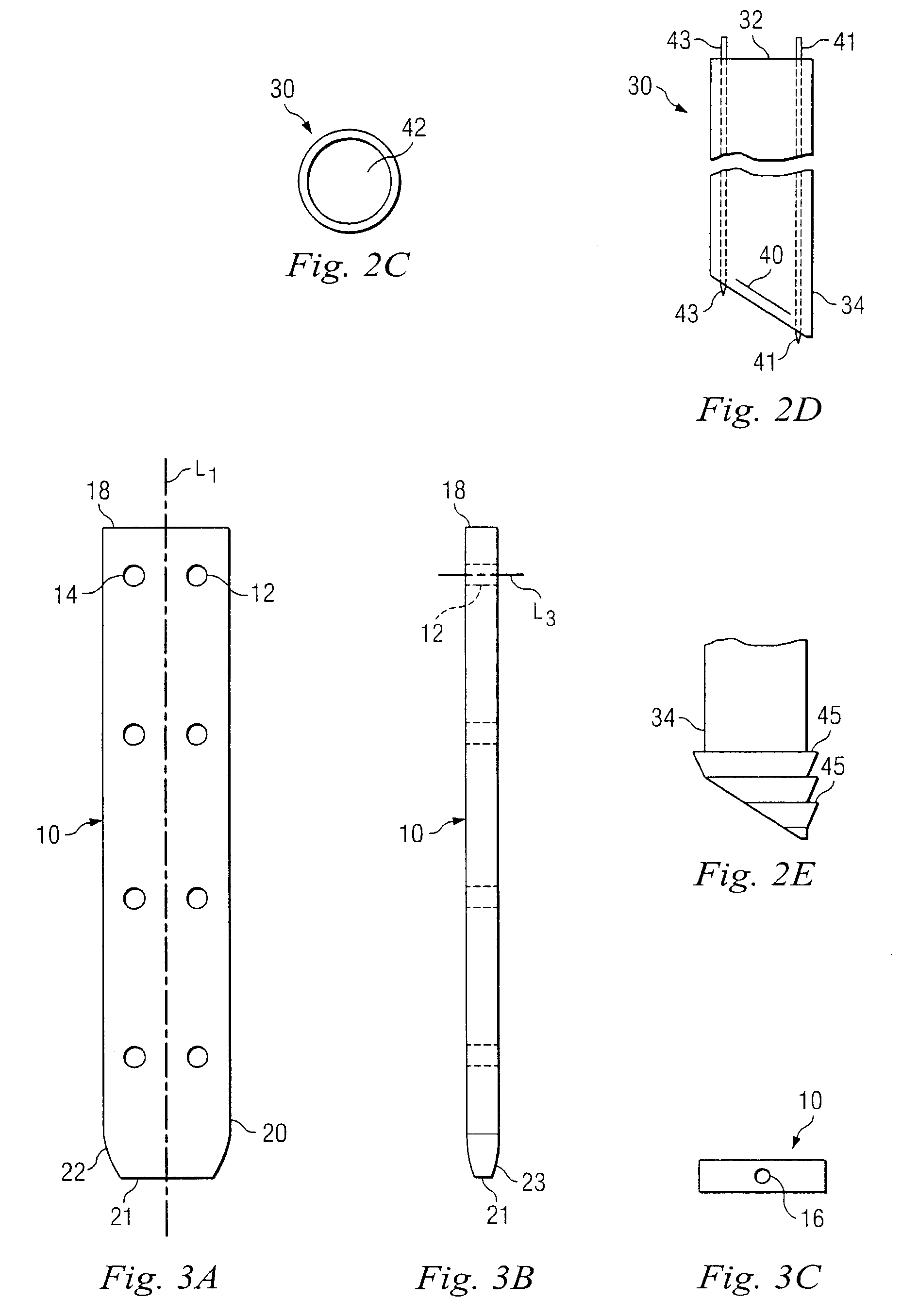
[0019]Referring now to FIGS. 2A through 2C, there is shown a protective sheath in accordance with one aspect of the present invention. Sheath 30 includes a proximal end 32 and an opposite distal end 34. Distal end 34 includes an extreme dist...


PUM


Abstract

The present invention provides a technique for percutaneous intramedullary fixation. A protective outer sheath is provided for internal fixation of the proximal tibia. Additionally, a unique intramedullary plate is provided that is adapted for percutaneous insertion into the intramedullary canal of a long bone. A plate holder is also provided that may be utilized through the outer sheath to drive and position a fixation plate within the intramedullary canal.

Description

CROSS REFERENCE[0001]This application claims priority from U.S. Provisional patent application Ser. No. 60 / 454,826, filed on Mar. 14, 2003, and entitled “PERCUTANEOUS FIXATOR AND METHOD OF INSERTION”BACKGROUND[0002]The present invention relates to skeletal fixation. In one aspect, it provides improved instruments, fixation members and methods of insertion for tibial fixation utilizing an intra-articular insertion.[0003]Tibial fixation utilizing elongated plates or rods disposed in the intramedullary canal or plating on the tibia cortex has been previously performed to provide fixation of the proximal tibia. In a traditional approach, a plate is placed on the periosteal cortex through an open or limited open surgical approach. Alternatively, the knee joint is flexed so that the surgeon can gain access to the proximal portion of the tibia intramedullary canal. In previous intramedullary approaches, the patella is moved laterally to provide direct access to the proximal portion of the ...

Claims


Application Information

Patent Timeline
Patent Type & Authority Applications(United States)
IPC IPC(8): A61B17/70A61B19/00A61B17/04A61B17/80A61B17/88
CPCA61B17/1703A61B17/1725A61B17/1735A61B17/72A61B17/1764A61B17/921A61B17/16A61B19/00A61B17/80A61B90/00A61B2017/564
Inventor COLE, J. DEAN
Owner COLE J DEAN
Why Eureka
Try Eureka