Motor for driving aircraft, located adjacent to undercarriage wheel

Active Publication Date: 2009-05-07
BOREALIS TECH LTD
View PDF6 Cites 61 Cited by
  • Summary
  • Abstract
  • Description
  • Claims
  • Application Information

AI Technical Summary

Problems solved by technology

However, this magnetic field configuration induces substantial rotor currents in the rotor windings, and the currents produce induction based torque to rotate the rotor.

Method used


Image

  • Motor for driving aircraft, located adjacent to undercarriage wheel
  • Motor for driving aircraft, located adjacent to undercarriage wheel
  • Motor for driving aircraft, located adjacent to undercarriage wheel

Examples


first embodiment

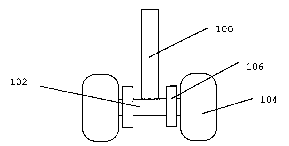
[0023]In the invention, shown in FIG. 1, a self-propelled aircraft undercarriage for driving an aircraft on the ground, is disclosed, comprising: an axle 102; a strut 100 supporting said axle; two wheels 104 rotatably mounted on said axle; and a drive means 106 for driving each said wheel. Said drive means is disk shaped and is external to said wheel. Said drive means is mounted on said axle between said strut and said wheel as shown in the figure.

[0024]Said strut is a supporting strut as is known in the art of aircraft undercarriages. It may be retractable, telescopically or otherwise, and may be made of a metal, metal alloy or any other suitable material.

[0025]Said axle and said wheel are also as known in the art of aircraft undercarriages and may be of any suitable construction and material. Said wheel may comprise a tire which is as known in the art and may be of any suitable construction and material.

[0026]Said drive means is preferably a high phase order electric induction mot...

third embodiment

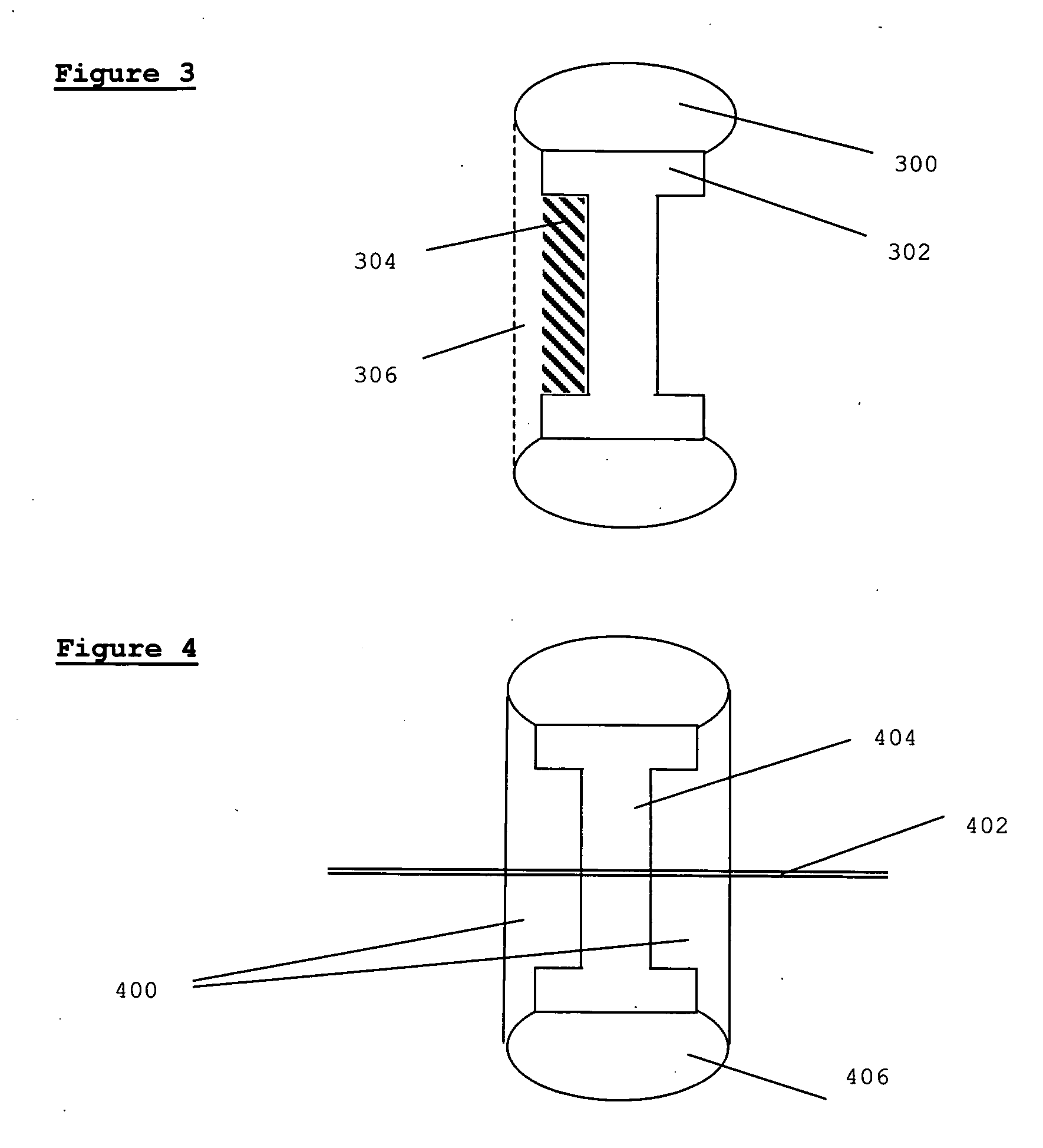
[0043]In the invention, shown in FIG. 4, two drive means 400 are mounted on the axle 402 for each wheel 404, one drive means being located on each side of the wheel. (Thus for an undercarriage arrangement consisting of two wheels, four drive means would be mounted). Tire 406 is mounted on wheel 404. The two drive means may be able to move towards and away from the wheel as required for engaging and disengaging, and in their position closest to the wheel may contact and clamp the wheel, acting as caliper brakes. This is preferably achieved using linear motor activation or may be achieved using hydraulics. Power may be fed to the drive means closest to the strut directly from the strut, and to that furthest from the strut through the axle. An advantage of this embodiment is that the maximum volume within the wheel space is occupied, without taking up extra space outside of the wheel. Thus stronger motors, able to provide more torque, can be fitted. Furthermore, the surface area of con...


PUM


Abstract

The invention disclosed is a self-propelled aircraft undercarriage for driving an aircraft on the ground, comprising: an axle; a strut supporting said axle; at least one wheel rotatably mounted on said axle; and drive means for driving said at least one wheel; characterized in that said drive means is disk shaped and is external to said wheel. In one embodiment of the invention, said drive means is mounted on said axle between said strut and said wheel. In a second embodiment, said drive means is mounted on said axle, on the side of said wheel furthest from said strut.

Description

CROSS-REFERENCE TO RELATED APPLICATIONS[0001]This application claims the benefit of Provisional Patent Application No. 61 / 002,079, filed Nov. 6, 2007.BACKGROUND OF THE INVENTION[0002]The use of separate motors to move aircraft on the ground is helpful since it avoids using the aircraft turbines or a separate tug to move the aircraft.[0003]U.S. Pat. No. 3,711,043 to Cameron-Johnson discloses an aircraft drive wheel having a fluid-pressure-operated motor housed within the wheel and two planetary gear stages housed in a gear box outboard of the motor, the final drive being transmitted from a ring gear of the second gear stage, which is inboard of the first stage, to the wheel through an output drive quill coupled, through a disc-type clutch if desired, to a flanged final drive member surrounding the inner end of the gear box and bolted to the wheel.[0004]U.S. Pat. No. 3,977,631 to Jenny discloses a wheel drive motor selectively coupled to an aircraft wheel through a rotatably mounted a...

Claims


Application Information

Patent Timeline
Patent Type & Authority Applications(United States)
IPC IPC(8): B64C25/50
CPCB64C25/40B64C25/001Y02T50/823B64C25/405Y02T50/80
Inventor COX, ISAIAH WATASWALITZKI, HANS JUERGENEDELSON, JONATHAN SIDNEY
Owner BOREALIS TECH LTD
Why Eureka
Try Eureka