
Inductor/transformer and manufacturing method thereof

a technology of transformers and transformers, applied in the direction of adaptive control, semiconductor/solid-state device testing/measurement, instruments, etc., can solve the problems of increased thickness of conductive layers within inductor layers, inability to reduce manufacturing process costs, etc., and achieve the effect of reducing substrate loss

Active Publication Date: 2009-05-07
AIROHA TECHNOLOGY CORPORATION
View PDF1 Cites 12 Cited by
  • Summary
  • Abstract
  • Description
  • Claims
  • Application Information

AI Technical Summary

Benefits of technology

The present invention provides a manufacturing process for an inductor / transformer that allows for the input of various parameters to a simulator for synthesizing and generating the desired design. The process includes manufacturing the inductor / transformer with a thickness of the conductive layers of less than 1 μm, using a process called a logic circuit. The invention also includes a method for performing a process variability analysis on the manufactured inductor / transformer to modulate its performance based on the results of the analysis. Additionally, the invention provides an inductor / transformer with a floating pattern shield to reduce substrate loss and integrate RFIC and high-density digital circuit into a SoC. The invention also allows for the integration of the inductor / transformer into a SiP with other components, such as a logic circuit, using a process called a logic circuit. The invention further includes a method for performing a process variability analysis on the manufactured inductor / transformer to improve its performance.

Problems solved by technology

One major drawback of foregoing the mentioned embodiment is the cost of the manufacturing process; it cannot be reduced because of the manufacturing and measuring of a variety of inductors.
Furthermore, the thickness of the conductive layer within the inductor is increased in order to improve the quality factor of the inductor, and it is more difficult to manufacture the inductor by way of the generic logic circuit process.

Method used


Image

  • Inductor/transformer and manufacturing method thereof
  • Inductor/transformer and manufacturing method thereof
  • Inductor/transformer and manufacturing method thereof

Examples


Embodiment Construction

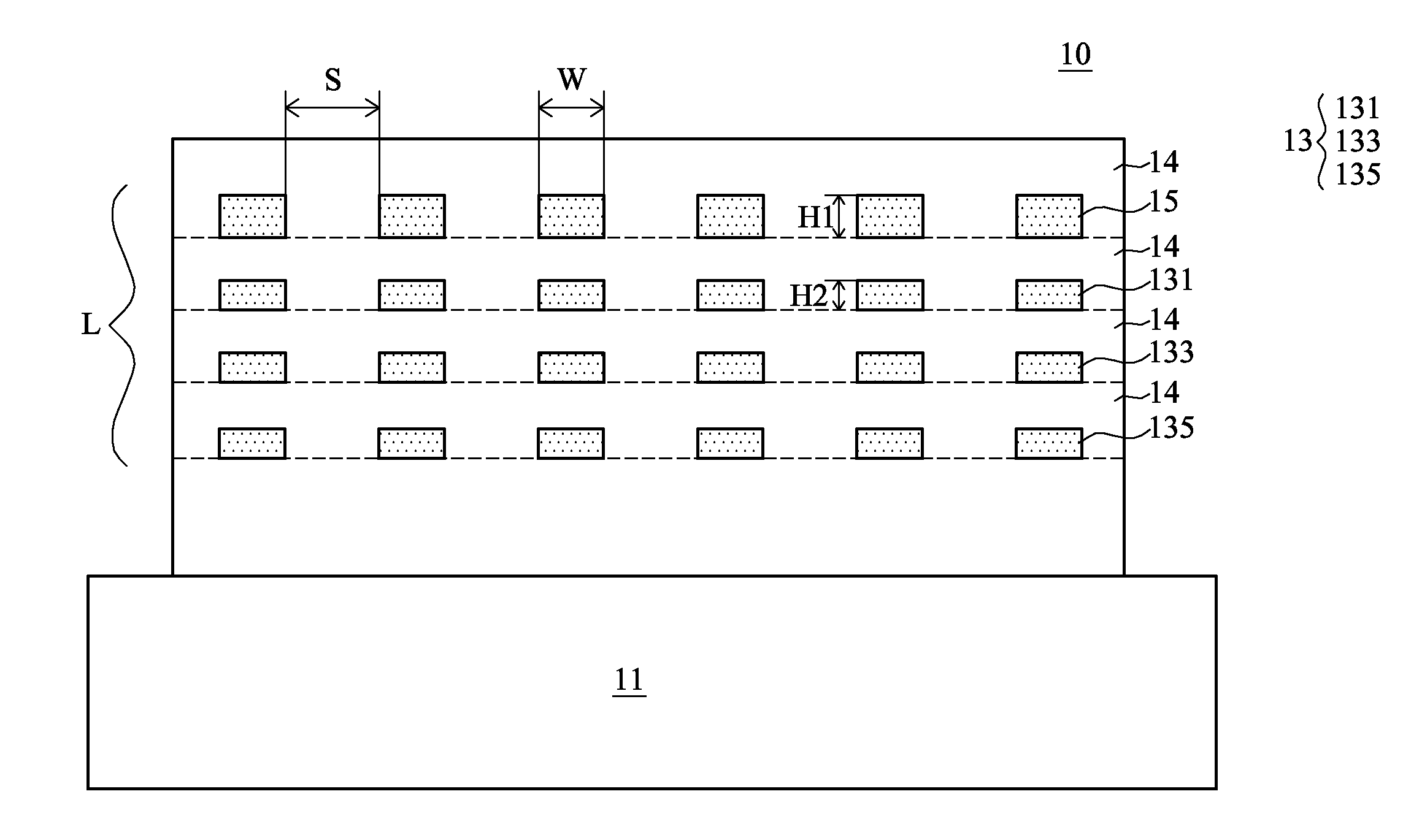
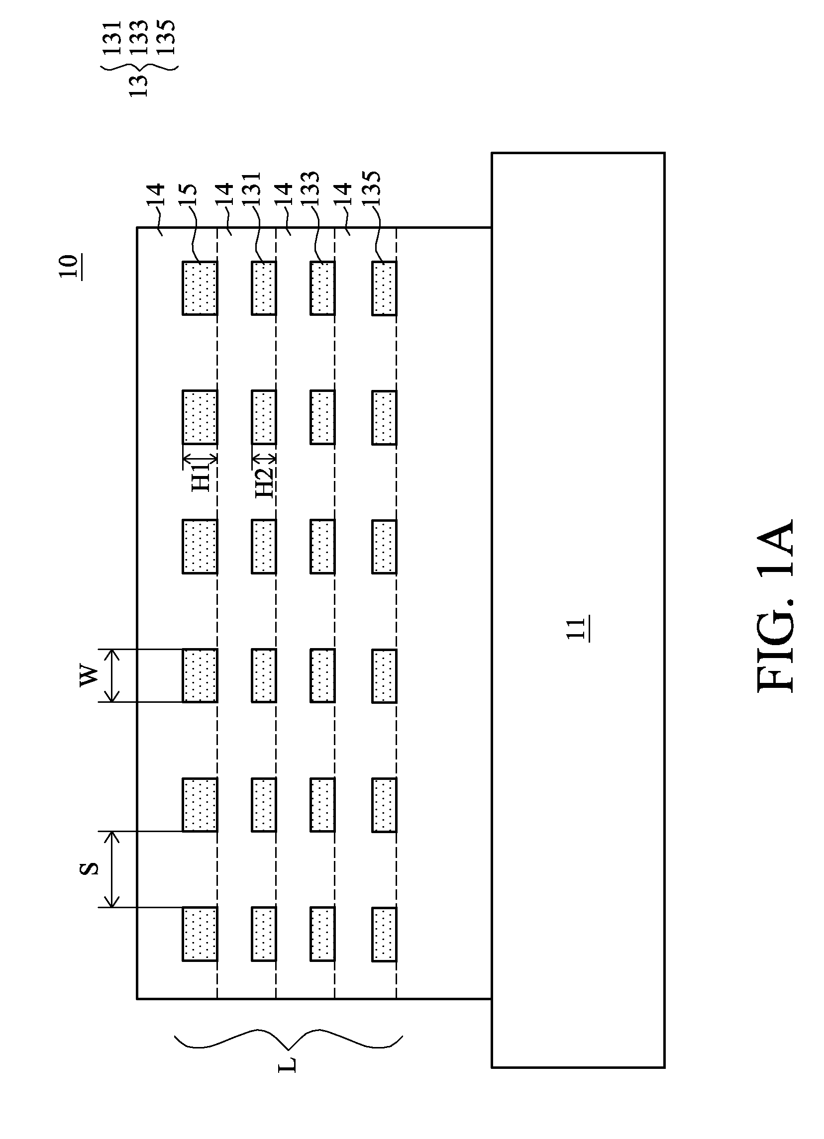
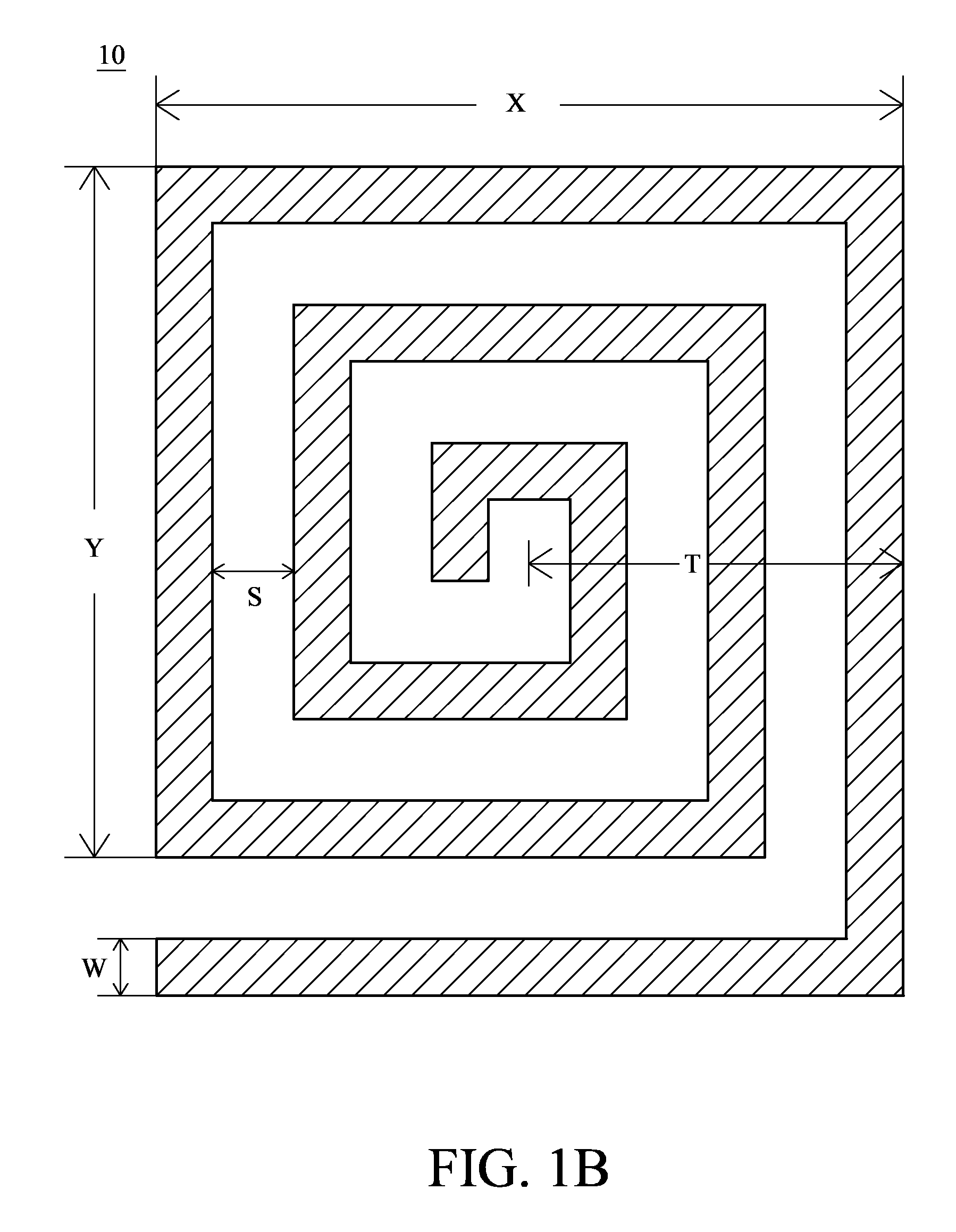
[0024]Referring to FIG. 1A, FIG. 1B, and FIG. 2, a cross-sectional view, a top view, and a flow chart illustrating the manufacturing process of the inductor / transformer according to an embodiment of the present invention, respectively, is disclosed. The inductor / transformer 10 comprises a substrate 11, at least one conductive layer 13, and a first conductive layer 15, wherein the conductive layer 13 is provided on the substrate 11, and the first conductive layer 15 is stacked on the conductive layer 13; moreover, the thicknesses (H1 / H2) of the conductive layer 13 and the first conductive layer 15 are both smaller than 1.0 μm.

[0025]A dielectric layer 14 is provided between the conductive layer 13 and the first conductive layer 15; furthermore, the dielectric layer 14 can be provided between the adjacent conductive layer 13, while the number of the conductive layer 13 is plurality. For example, the conductive layer 13 comprises a second conductive layer 131, a third conductive layer 1...


PUM

PropertyMeasurementUnit
thicknessesaaaaaaaaaa
conductiveaaaaaaaaaa

Abstract

A manufacturing method for the inductor / transformer is disclosed. A simulator is used to simulate the inductance, the quality factor, and the self-resonance frequency of said inductor / transformer to generate at least one group of the area size, the number of the conductive layer, the line width, the number of turns, and / or the line space of the conductive layers and the first conductive layer; the inductor / transformer is manufactured according to the factors. Thereafter, the Monte-Carlo simulation is used to initiate the process variability analysis of the factors of the conductive layer and the first conductive layer, and the geometric size of the inductor / transformer can be modulated according to the results of the process variability analysis during the manufacturing process, such that the inductor / transformer can be manufactured by the process of the generic logic circuit.

Description

BACKGROUND OF THE INVENTION[0001]1. Technical Field[0002]The present invention is related to an inductor / transformer and the manufacturing method thereof, wherein the inductance, quality factor, and self-resonance frequency of the inductor / transformer can be input into a simulator to proceed with the simulation process.[0003]2. Description of the Prior Art[0004]The wide application of the wireless communication device improves the manufacturing process and the design of the RFIC, such as the reduction of chip size, improvement of the yield, and so on. In general, transistors and passive elements, such as inductors, play an essential role in the RFIC; for example, the inductor is provided within the filter and the amplifier of the RFIC.[0005]In the design and manufacturing processes of the circuit, it is of great importance to consider the inductance, quality factor (Q), and self-resonance frequency (Fsr) of the inductor. For example, an inductor with a high quality factor can store ...

Claims


Application Information

Patent Timeline
Patent Type & Authority Applications(United States)
IPC IPC(8): H01F27/28H01L21/66H01F27/30H01F41/04
CPCH01F17/0013H01L23/5227H01L23/5225H01F41/041H01L2924/0002H01L2924/00
Inventor CHEN, SHENG-YOWTSENG, KUO-YU
Owner AIROHA TECHNOLOGY CORPORATION
Learn More