Current switch with automatic calibration

a current switch and automatic calibration technology, applied in the direction of resistance/reactance/impedence, testing circuits, instruments, etc., can solve the problems of time-consuming and laborious calibration of large numbers of widely dispersed current sensors or even one sensor remotely located from the controller

Active Publication Date: 2009-05-07
VERIS INDS
View PDF99 Cites 50 Cited by
  • Summary
  • Abstract
  • Description
  • Claims
  • Application Information

AI Technical Summary

Problems solved by technology

However, both the frequency and the voltage of the variable frequency drive's output vary producing a substantial variation in the current to the motor.
Calibrating large numbers of widely dispersed current sensors or even one sensor that is remotely located from the controller can be time consuming and tedious.

Method used


Image

  • Current switch with automatic calibration
  • Current switch with automatic calibration
  • Current switch with automatic calibration

Examples


Embodiment Construction

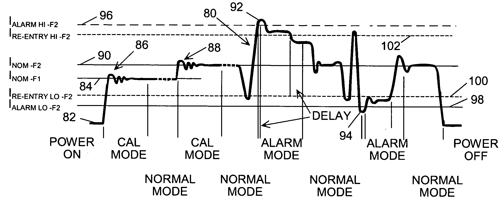
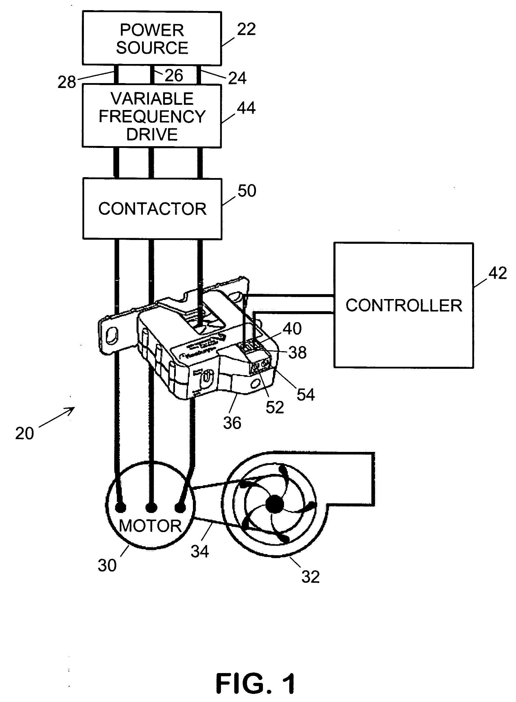
[0014]Referring in detail to the drawings where similar parts are identified by like reference numerals and referring more particularly to FIG. 1, an exemplary electrical system 20 includes an electrical load that is connectable to a power source 22, typically an electric power distribution grid, by power cables 24, 26, 28. By way of examples, electrical loads may include valves, heaters, relays, lights, and motors which may be used to drive pumps, fans, compressors, etc. In the exemplary system, the electrical load comprises a motor 30 that is drivingly connected to a mechanical load, a fan 32, by a drive belt 34. A current switch 36 monitors the current flow in one of the power cables. When the fan motor is running and current is flowing in the power cable, a current sensor in the current switch is electromagnetically linked to the power cable current and outputs a signal reflecting the magnitude and frequency of the current in the cable. If the magnitude of the current is within ...


PUM


Abstract

A current switch is automatically calibrated when a flow of electric current is initiated in a power cable.

Description

CROSS-REFERENCE TO RELATED APPLICATIONS[0001]This application claims the benefit of U.S. Provisional App. No. 60 / 993,312, filed Sep. 10, 2007.BACKGROUND OF THE INVENTION[0002]The present invention relates to a current switch for monitoring a current level in an electrical circuit and enabling an alarm if the current level is abnormal and, more particularly, to a current switch that is automatically calibrated to the current level of a circuit when it is installed in the circuit.[0003]Many industrial and commercial environments utilize large numbers of devices that are electrically powered. The operation of these devices, for example fans, pumps, compressors and heaters, can be important to the protection of valuable property and successful completion of processes that may involve costly or hazardous equipment, operations or materials. These devices may be stand-alone devices controlled by a local controller, but are often widely dispersed components of an integrated and, commonly, a...

Claims


Application Information

Patent Timeline
Patent Type & Authority Applications(United States)
IPC IPC(8): G08B21/00
CPCH02H7/0833H02H3/006
Inventor HUNTER, PHILLIPBERNKLAU, JAMESBRUNO, DAVID A.
Owner VERIS INDS
Why Eureka
Try Eureka