
Auxiliary supporting structure for presses, and plastics molding press equipped with such a structure

a technology of supporting structure and presses, which is applied in the direction of presses, ceramic shaping apparatus, auxiliaries shaping apparatus, etc., can solve the problems of incompatible injection molding method, inability to economically achieve injection molding, and damage to the half-mold, so as to achieve the effect of cheaper and easier production

Inactive Publication Date: 2009-05-07
INGLASS SPA
View PDF7 Cites 18 Cited by
  • Summary
  • Abstract
  • Description
  • Claims
  • Application Information

AI Technical Summary

Benefits of technology

[0010]It is an object of the present invention to provide a plastics injection-compression molding press that is cheaper and easier to produce than multicylinder presses.

Problems solved by technology

In addition, when working with exceptionally high injection pressures, and when the plastic material injection points are arranged asymmetrically inside the mold cavity, the half-molds are subjected at the injection stage to severe, highly unbalanced, pulsating mechanical forces that tend to rotate the half-molds with respect to each other, and which, if not counteracted by the press, may affect alignment of the two platens, thus resulting in damage to the half-molds and / or to the supporting columns of the press guiding the movement of one of the two mold platens.
Unfortunately, multicylinder presses of the above type are extremely expensive to produce, thus making injection-compression molding economically unfeasible, despite the better quality and surface finish of the end products; whereas cheaper toggle presses or similar, on account of the much simpler platen actuating mechanism, fail to provide for combined control of the position, pressure, and orientation (parallelism) of the two mold platens, and are therefore incompatible with the injection-compression molding method as described above.

Method used


Image

  • Auxiliary supporting structure for presses, and plastics molding press equipped with such a structure
  • Auxiliary supporting structure for presses, and plastics molding press equipped with such a structure
  • Auxiliary supporting structure for presses, and plastics molding press equipped with such a structure

Examples


Embodiment Construction

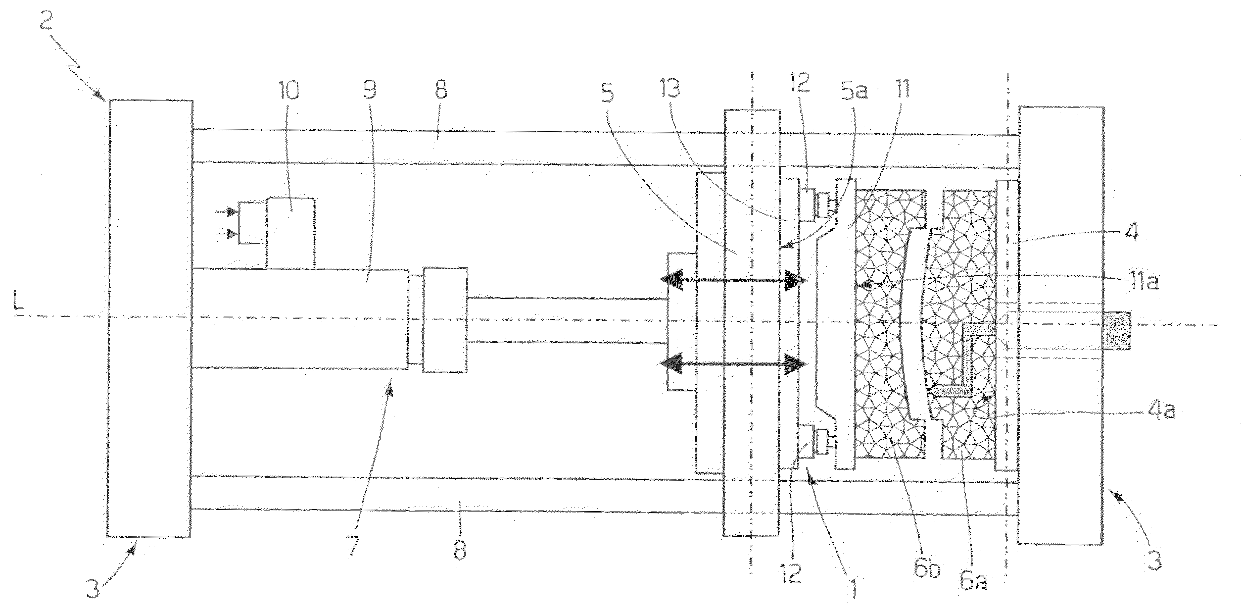
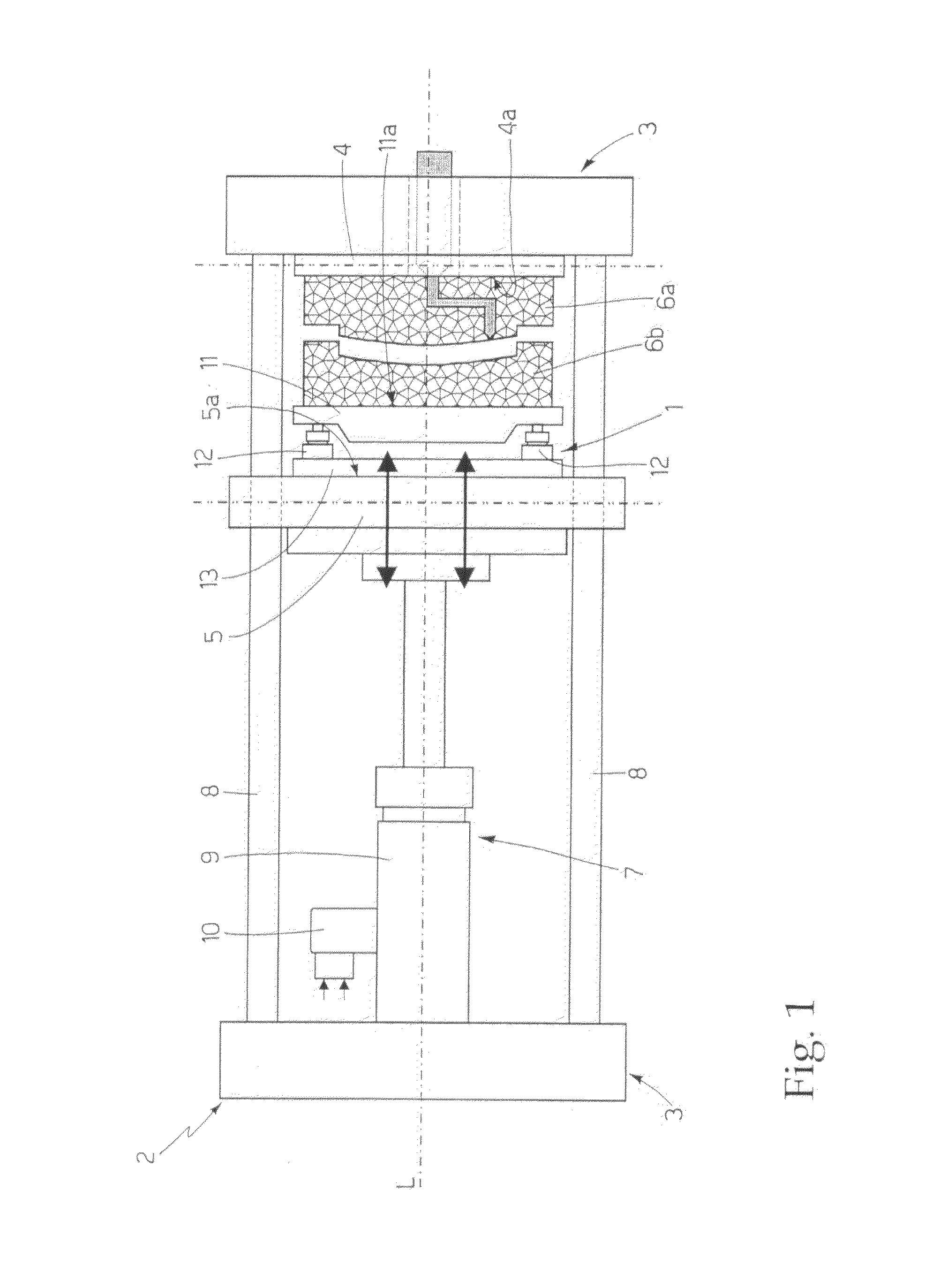
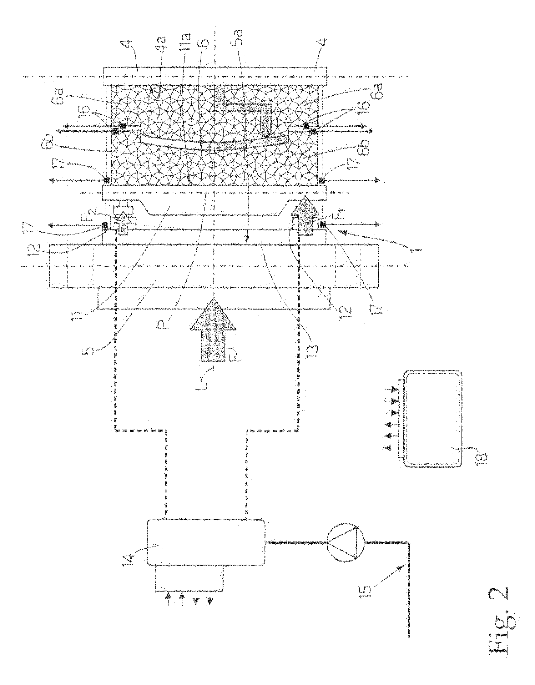
[0016]Number 1 in FIG. 1 indicates as a whole an auxiliary supporting structure for presses, designed to actively compensate unbalanced loads, and specifically for assembly to a preferably, though not necessarily, horizontal-axis plastics molding press 2.

[0017]Press 2 substantially comprises an on-floor supporting frame 3; and two mold platens 4, 5, which are fitted to supporting frame 3 of the machine, are aligned along the longitudinal axis L of the machine, perfectly parallel and facing each other, so as that the lying planes of said mold platens are perpendicular to longitudinal axis L; are designed to move one against the other in a direction parallel to longitudinal axis L of the press; and are each designed so that its front surface 4a, 5a—i.e. the surface directly facing the other mold platen 4, 5—can support, firmly but in easily removable manner, one of the two half-molds 6a, 6b, which, when closed, form, at the join, a mold cavity 6 negatively reproducing the shape of the...


PUM


Abstract

An auxiliary supporting structure for presses, having an auxiliary mold platen having a front surface designed to firmly, but removably, support a half-mold; a number of hydraulic supporting cylinders, which project from the rear of the auxiliary mold platen, in a direction parallel to a reference axis perpendicular to the plane of the auxiliary mold platen; mounting means for firmly, but removably, fixing the hydraulic cylinders to the front surface of a movable mold platen of the press; a hydraulic distributor for regulating pressurized-oil flow to and from each hydraulic cylinder independently of the others; and an electronic central control unit for controlling the hydraulic distributor as a function of signals from a number of external sensors, to enable the hydraulic cylinders to instantaneously compensate any asymmetric distribution of the mechanical forces exerted on the half-mold as the plastic material is injected.

Description

[0001]The present invention relates to an auxiliary supporting structure for presses, and to a plastics molding press equipped with such a structure.[0002]More specifically, the present invention relates to an auxiliary supporting structure for plastics injection-compression molding presses, to which the following description refers purely by way of example.BACKGROUND OF THE INVENTION[0003]As is known, in injection-compression molding, the molten plastic material is injected into the mold cavity—negatively reproducing the shape of the part for molding—when the two half-molds—eventually defining the mold cavity when closed—are still open and moving towards each other.[0004]The main advantage of injecting the plastic material beforehand into the mold cavity and compacting it as the half-molds close is that it allows the plastic material to fill even the smallest recesses of even highly elaborate mold cavities before it begins to set.[0005]Presses employing this method must therefore b...

Claims


Application Information

Patent Timeline
IPC IPC(8): B29C45/76
CPCB29C33/20B29C43/58B29C45/561B29C45/661B29C45/67B29C2043/5808B30B15/007B29C2945/76006B29C2945/76083B29C2945/76254B29C2945/76387B29C2945/76568B29C2043/5858
Inventor BAZZO, MAURIZIOGIRELLI, DARIORUBERT, LORENZO
Owner INGLASS SPA
Learn More