Fast Settling Radio Receiver Automatic Gain Control System

Active Publication Date: 2009-05-07
MICREL
View PDF7 Cites 13 Cited by
  • Summary
  • Abstract
  • Description
  • Claims
  • Application Information

AI Technical Summary

Benefits of technology

[0012]In accordance with another embodiment of the present invention, an AGC method for a radio receiver circuit includes, when a strong radio signal is first received and a relatively high output signal is generated by the variable gain amplifier of the radio receiver circuit, decreasing the gain of the variable gain amplifier at a first, relatively fast rate until output signal's voltage level is equal to an intermediate reference signal voltage level (which is greater than the target voltage level). Then, when the output signal voltage level has dropped to level between the intermediate reference signal and target voltage level, further decreasing the gain of the variable gain amplifier at a second, relatively slow rate until the output signal voltage level equals the target voltage level. That is, during a first phase of the AGC process, the output voltage is settled at a relative fast rate until the output signal reaches the intermediate reference signal, then the output voltage continues to settle during the second phase at the slower time rate until the output voltage equals the target reference signal. Thus, the present invention changes the AGC gain control signal much more rapidly than conventional systems using only a single rate without adversely affecting the modulated information after the settling phase because the fast settling comparator is not activated once the signal peaks have

Problems solved by technology

In other embodiments, the current level of the second gain control signal components may be substantially equal to the current level of the first gain control signal components, but this would only double the res

Method used


Image

  • Fast Settling Radio Receiver Automatic Gain Control System
  • Fast Settling Radio Receiver Automatic Gain Control System
  • Fast Settling Radio Receiver Automatic Gain Control System

Examples


Example

DETAILED DESCRIPTION OF THE DRAWINGS

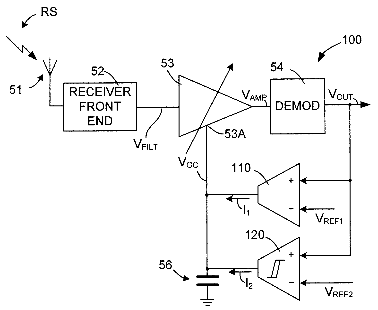
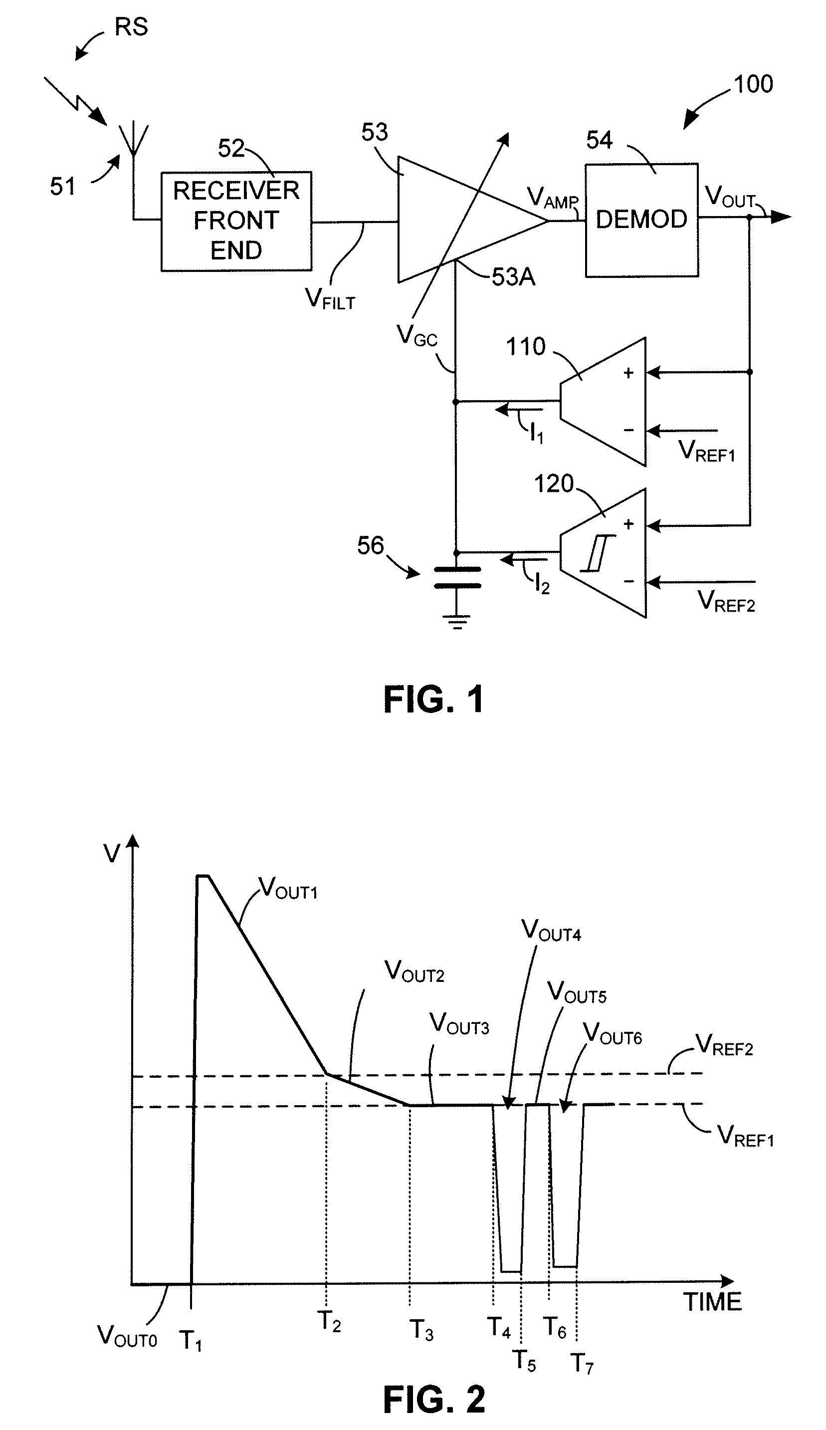
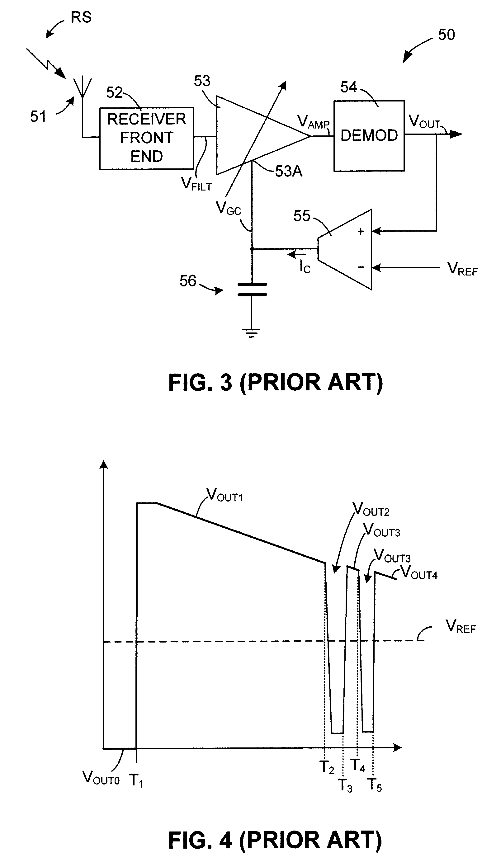
[0018]The present invention relates to an improvement in radio receiver circuits. The following description is presented to enable one of ordinary skill in the art to make and use the invention as provided in the context of a particular application and its requirements. The terms “coupled” and “connected”, which are utilized herein, are defined as follows. The term “connected” is used to describe a direct connection between two circuit elements, for example, by way of a metal line formed in accordance with normal integrated circuit fabrication techniques. In contrast, the term “coupled” is used to describe either a direct connection or an indirect connection between two circuit elements. For example, two coupled elements may be directly connected by way of a metal line, or indirectly connected by way of an intervening circuit element (e.g., a capacitor, resistor, inductor, or by way of the source / drain terminals of a transistor). Various modificat...


PUM


Abstract

A fast settling AGC system includes a “fast settle” comparator that facilitates fast settling of strong radio receiver output signals from a maximum to an intermediate voltage level at the start of each transmission burst, and a “normal” AGC comparator that further settles the output signal from the intermediate voltage level to a desired target output voltage level at a slower “normal” rate. The gain control signal components generated by both the “fast settle” comparator and the “normal” AGC comparator are summed and applied to the gain control terminal of a variable gain amplifier. The gain control signal component generated by the “fast settle” comparator has a higher current level than the gain control signal component generated by the “normal” comparator, but is terminated when receiver output signal drops to the intermediate voltage level.

Description

FIELD OF THE INVENTION[0001]This invention relates to radio receiver circuits, and more particularly to radio receiver circuits including automatic gain control.BACKGROUND OF THE INVENTION[0002]FIG. 3 is a simplified block diagram illustrating a conventional radio receiver 50 including an antennae 51 for received a radio signal RS, a receiver front end circuit 52 for converting radio signal RS into a filtered (electrical) signal VFILT, a variable gain amplifier 53 and a demodulator 54 for demodulating filtered signal VFILT to produce an output signal VOUT that is used, for example, to represent digital pulses (note that the present invention is of most benefit with digital pulse signals), or to generate music or other sounds representing information carried by radio signal RS. The specific functions performed by receiver front end circuit 52, amplifier 53, and demodulator 54 are well known in the art, and therefore a more detailed description is omitted for brevity.[0003]It is a com...

Claims


Application Information

Patent Timeline
IPC IPC(8): H04B1/16H03F3/45H03G3/20H04B17/40
CPCH03G3/3052
Inventor EXETER, GEORGE R.
Owner MICREL
Why Eureka
Try Eureka