
Sternal Clamp

Inactive Publication Date: 2009-05-07
BURKE SHAWN M
View PDF7 Cites 172 Cited by
  • Summary
  • Abstract
  • Description
  • Claims
  • Application Information

AI Technical Summary

Benefits of technology

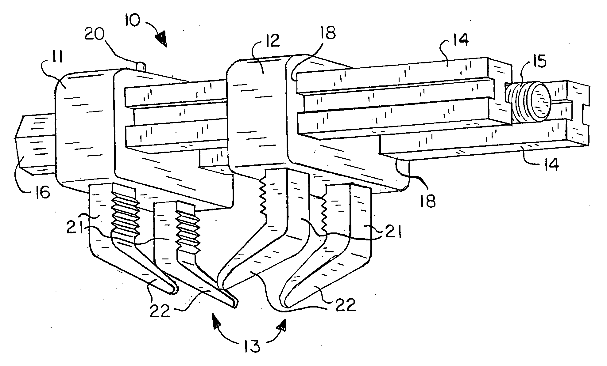
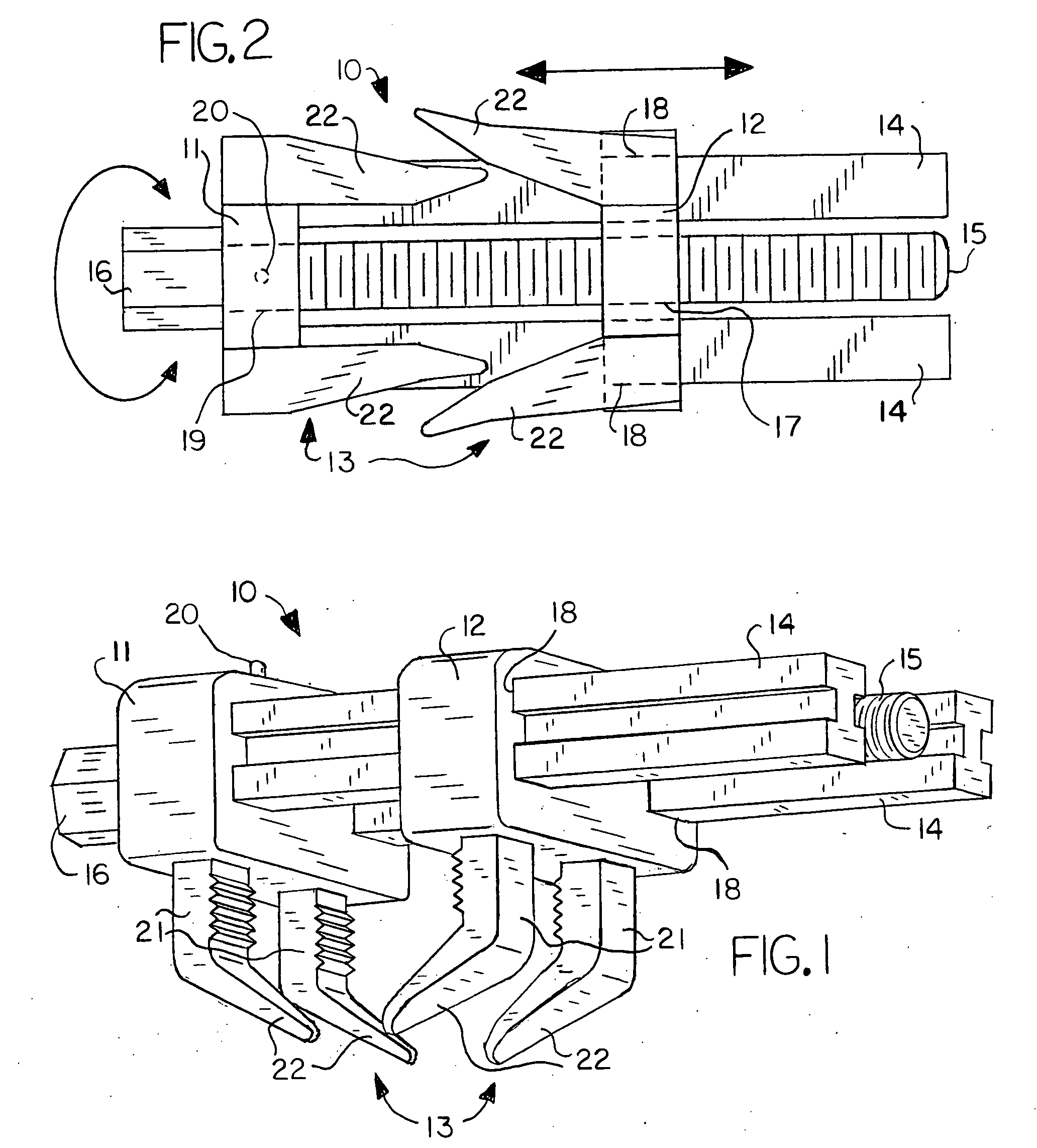
[0008]The invention is in general a sternal closure clamp device for post-operatively closing, securing and supporting a patient's sternum that has been longitudinally severed into two sternal halves. The sternal clamp generally comprises two body members each having a pair of spaced, sternum-engaging engagement members extending from the body member. A pair of parallel guide beam members is affixed to a first body member, the guide beam members preferably being disposed to either side of a threaded rod member, which is retained within the first body member in a manner that allows the rod member to be rotated relative to the first body member, such as by passage through an unthreaded bore. The guide beam members are of a cross-sectional I-beam configuration in order to increase the overall rigidity of the device while reducing the overall mass. A drive member is provided on the outer end of the rod member to receive a drive tool for rotating the rod member.
[0009]The second body member is provided with a threaded bore that receives the turn screw member, and is further provided with a pair of guide beam apertures sized to receive the guide beam members in a manner that allows the second body member to move longitudinally relative to the guide beam members. With this construction, rotation of the threaded rod member in a first direction increases the distance between the body members, while rotation of the turn screw member in the second direction decreases the distance between the body members. Additional means to lock or fix the rod member in a non-rotatable status such that the separation distance between the body members may be fixed and secured when the body members are fully contracted about the sternal halves may also be present.

Problems solved by technology

Because high strength and rigidity are crucial characteristics of the sternal clamp, the main bodies of the clamps are often over-engineered in terms of thickness and mass.
Known mechanisms for accomplishing this are often excessively complicated or result in loose components that can be dropped and lost within the chest cavity.

Method used


Image

  • Sternal Clamp
  • Sternal Clamp

Examples


Embodiment Construction

[0013]With reference to the drawings, the invention will now be described in detail with regard for the best mode and the preferred embodiment. The invention is a sternal closure clamp device used to close, secure and support a sternum post-operatively, the sternum having been severed longitudinally into left and right lateral sternal halves to provide access to the interior of the chest.

[0014]The sternal clamp 10 generally comprises two opposing body members, a first body member 11 and a second body member 12, each having connected thereto a pair of spaced, sternum-engaging, engagement members 13 extending posteriorly from the body members 11 and 12. A pair of parallel guide beam members 14 is affixed to the first body member 11, the guide beam members 14 being disposed to either side of a threaded rod member 15, which is retained within a non-threaded centralized bore 19 in the first body member 11 in a manner that allows the rod member 15 to be rotated relative to the first body ...


PUM


Abstract

A sternal closure clamp for securing and retaining longitudinally divided halves of a sternum, the clamp having a pair of body members each having a pair of engagement members, a pair of guide beam members affixed to a first of the body members and extending through a second of the body members, the guide beam members having an I-beam cross-sectional configuration, and a threaded rod member retained by the first body member and passing through the second body member, whereby rotation of the rod member in a first direction increases the distance between the body members and rotation in a second direction decreases the distance between the body members.

Description

[0001]This patent application claims the benefit of U.S. Provisional Patent Application Ser. No. 61 / 001,390, filed Nov. 1, 2007.BACKGROUND OF THE INVENTION[0002]This invention generally relates to devices used to rejoin a human sternum that has been severed longitudinally, and more particularly relates to such devices that function in a clamping manner to retain the severed sternum portions in a closed and abutting relationship post-operatively.[0003]It is often necessary in surgical operations to longitudinally sever the patient's sternum so that the ribs may be spread to provide access to internal organs such as the heart. It is then necessary to secure the sternum halves together for post-operative recovery. Various closure techniques are used to accomplish this task. For example, holes may be drilled into the sternum halves and suture material passed through and tightened to cinch the sternum halves together. Apertured plates may be added to further rigidify the sternum post-ope...

Claims


Application Information

Patent Timeline
IPC IPC(8): A61B17/04
CPCA61B17/08A61B2017/088A61B17/823
Inventor BURKE, SHAWN M.
Owner BURKE SHAWN M
Learn More