
Foldable, portable trauma treatment and monitoring patient platform

a patient platform and portable technology, applied in the field of portable emergency care devices, can solve the problems of shortening the treatment window, affecting the treatment effect, and the inability to meet the constraints, so as to facilitate the movement of the platform, and enhance the portability

Inactive Publication Date: 2009-05-14
MEDFLEX
View PDF4 Cites 8 Cited by
  • Summary
  • Abstract
  • Description
  • Claims
  • Application Information

AI Technical Summary

Benefits of technology

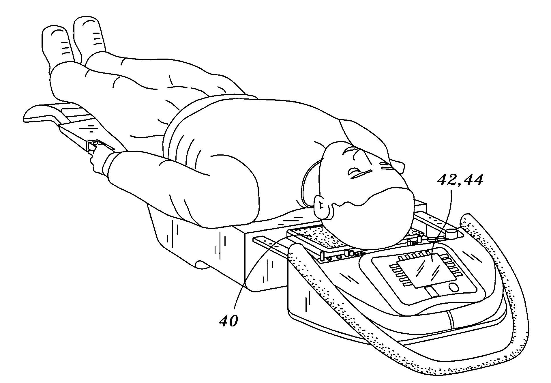
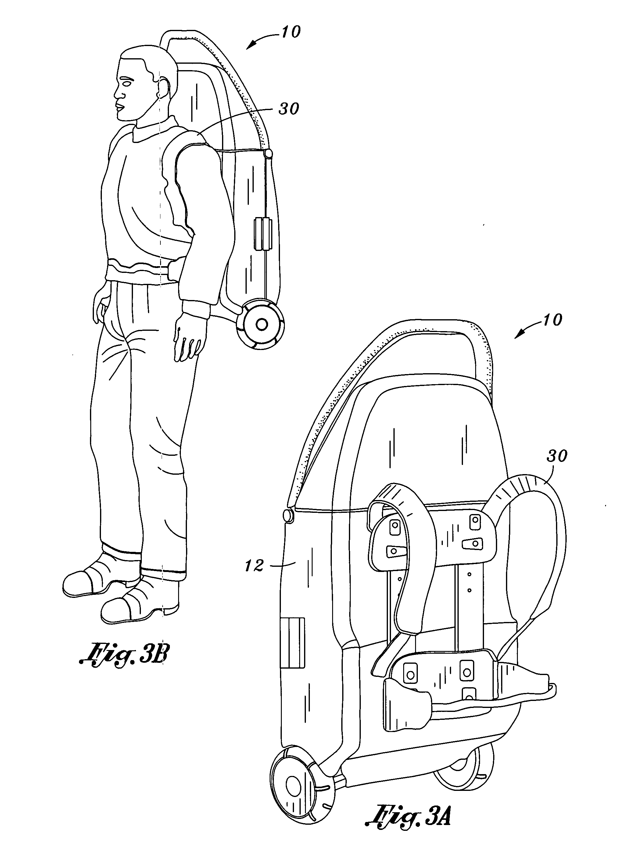
[0012]The present invention provides a highly portable trauma treatment and monitoring patient platform. The patient platform may be carried to the site of the injury and operated by one person. The present invention will greatly enhance emergency medical care, particularly in remote locations. The present invention may be of particular value when pre-deployed to areas of expectant traumatic injury such as combat forward aid stations, medivac units, civil disaster relief caches, or austere environments without extensive rapid response capability such as rural or maritime search and rescue. The present invention may also be particularly useful as a simplified emergency room back-up. In particular, the device may be stored in a closet and used when needed.
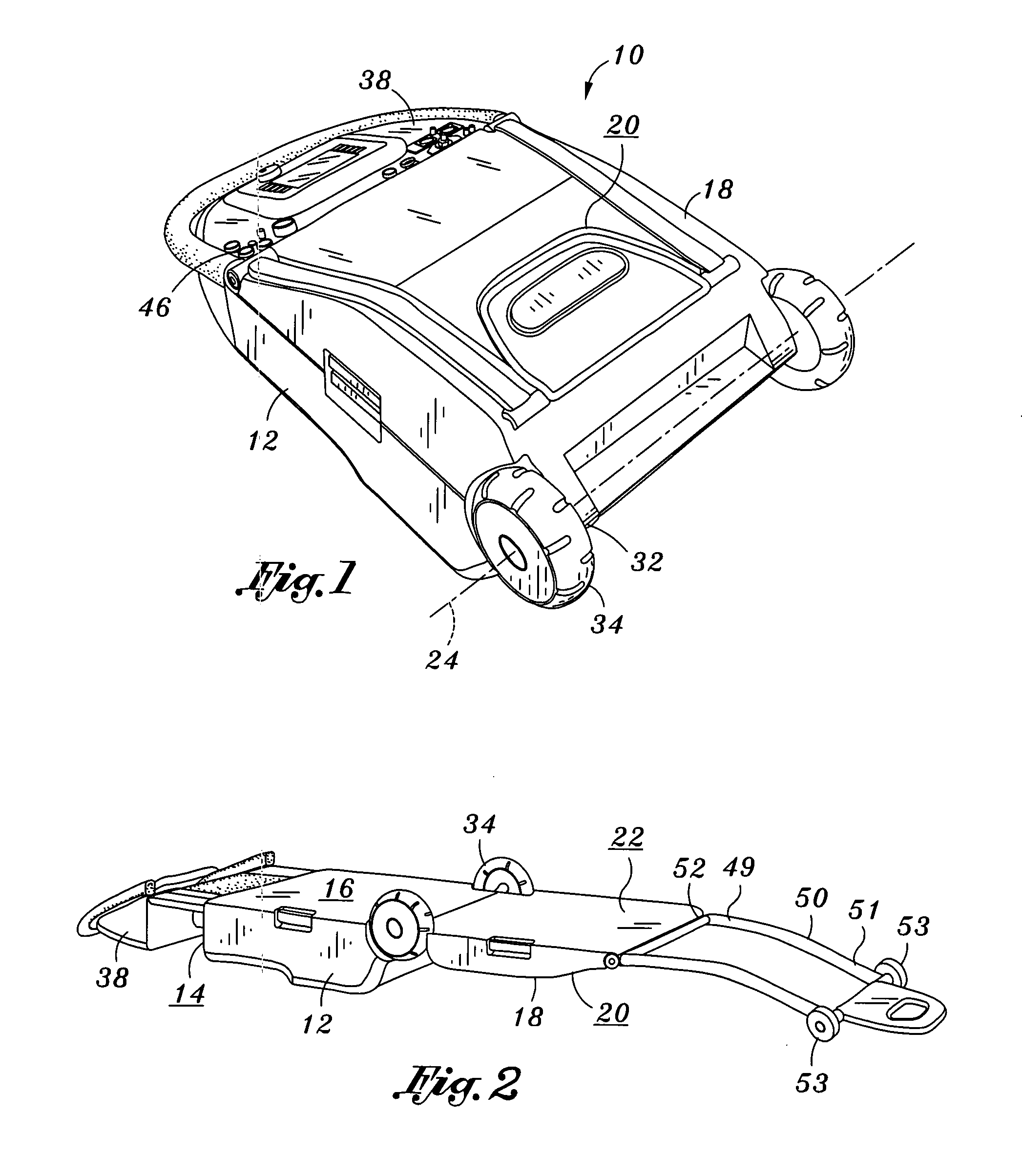
[0014]The patient platform may include additional accessories to further enhance its portability. For instance, the patient platform may include at least one strap coupled to the upper housing body to enable a medical provider to carry the patient platform when in the closed orientation. In addition, the patient platform may include a wheel to facilitate movement of the platform. A wheel may be disposed substantially adjacent to the pivoting axis. The wheel may be coupled to the upper or lower housing body. Such a wheel may facilitate platform movement when the platform is in the closed orientation and the partially open orientation.

Problems solved by technology

It is during this transportation period where a patient's condition may worsen because of the lack of medical equipment available to the emergency response team.
Many times, this time constraint cannot be met due to various reasons.
Although this problem occurs frequently in civilian situations, it may be magnified in battlefield conditions, where significant injuries and disease commonly occur.
The degree of injury and disease encountered on the battlefield shortens the treatment window.
In addition, soldiers are often in remote, war-torn areas, or areas which are not easily accessible by vehicle, making it very difficult to respond to those requiring medical attention.
Although these instruments are helpful in treating and transporting the patient, carrying such instrumentation to the patient's location may be difficult.
For instance, the defibrillator may require additional personnel to hand-carry the device during transport because there may be no space to stow it.
Although recent advances in technology have greatly enhanced emergency care and response, current systems are typically large and may require at least two medical care providers to transport the device to the patient's location.
This requirement may severely limit the range of medical care that may be provided to a patient.
This is especially true in the case of natural disasters and battlefield environments where vehicle transport may not be possible.
Although individual medical devices, such as a defibrillator may be carried to the patient, current systems which integrate numerous medical devices are too large to be carried by one individual.
In addition, certain medical providers may have stretchers, but may not have medical monitoring / treatment equipment.
Furthermore, stretchers and equipment may be stored separately in different locations, making it difficult to quickly and adequately respond in emergency situations.

Method used


Image

  • Foldable, portable trauma treatment and monitoring patient platform
  • Foldable, portable trauma treatment and monitoring patient platform
  • Foldable, portable trauma treatment and monitoring patient platform

Examples


Embodiment Construction

[0031]The detailed description set forth below is intended as a description of the presently preferred embodiment of the invention, and is not intended to represent the only form in which the present invention may be constructed or utilized. The description sets forth the functions and sequences of steps for constructing and operating the invention. It is to be understood, however, that the same or equivalent functions and sequences may be accomplished by different embodiments and that they are also intended to be encompassed within the scope of the invention.

[0032]The present invention is a lightweight, compact system of integrated medical, data and / or communication systems packaged to facilitate and support basic commonly accepted technological trauma treatment and care for a critically injured patient. This package may be implemented as a durable housing containing an assortment of subsystem units representing a basic set of diagnostic, therapeutic and data management functionali...


PUM


Abstract

There is provided a foldable, portable, trauma treatment and monitoring patient platform. The patient platform includes an upper housing body including a top surface and an upper patient support surface. The patient platform also includes a lower housing body including a rear surface and a lower patient support surface. The upper and lower patient support surfaces are cooperative to collectively support a patient. The lower housing and upper housing are in pivotal communication to enable selective articulation about a pivoting axis between a closed orientation and an open orientation. In the closed orientation, the upper patient support surface is substantially flush with the lower patient support surface. In the open orientation, the upper patient support surface and lower patient support surface are substantially co-planar. A bay capable of receiving at least one medical monitoring / treatment unit is located within at least one of the upper and lower housing bodies.

Description

CROSS-REFERENCE TO RELATED APPLICATIONS[0001]Not Applicable.STATEMENT RE: FEDERALLY SPONSORED RESEARCH / DEVELOPMENT[0002]Not ApplicableBACKGROUND[0003]The present invention relates in general to portable emergency care devices. More particularly, the invention relates to a foldable, man-portable, trauma treatment and patient monitoring patient platform for use by an initial response medical care provider.[0004]Sudden injury or disease may happen at a moment's notice. At the onset of such injury or disease, a patient often calls for the aid of an emergency response team. Upon arrival, members of the emergency response team assess the situation and diagnose the patient's condition. Oftentimes, patients cannot be sufficiently treated in the field, and require transport to a hospital or similar patient care center where more sophisticated equipment is readily available. It is during this transportation period where a patient's condition may worsen because of the lack of medical equipment...

Claims


Application Information

Patent Timeline
IPC IPC(8): A61G7/07A61G7/10A61G7/075
CPCA61G1/013A61G1/017A61G13/107A61G13/105A61G1/04
Inventor BARNETT, PETER ANDREWKNEALE, TODD DOUGLASALEXANDER, STEVEN BRUCEDOMAE, TERRANCE PAUL
Owner MEDFLEX
Learn More