Ink Discharging Apparatus and Ink Discharging Method

a technology of ink discharging apparatus and ink, which is applied in the direction of printing, instruments, optics, etc., can solve the problems of increasing the size of the substrate, reducing the time required for discharging ink onto all of the ink discharging targets, and being difficult to achieve the effect of shortening the processing time for discharging ink, and reducing the number of times

Inactive Publication Date: 2009-05-14
SHARP KK
View PDF7 Cites 14 Cited by
  • Summary
  • Abstract
  • Description
  • Claims
  • Application Information

AI Technical Summary

Benefits of technology

[0016]As discussed above, the ink discharging apparatus of the present invention is arranged so that the ink discharge means discharges ink onto neighboring ink discharge targets among plural ink discharge targets, by a single scanning movement with respect to the neighboring ink discharge targets. This makes it possible to reduce the number of times the ink discharge means moves to the ink discharge targets, as compared to the conventional arrangement in which ink is individually discharged to each ink discharge target. As a result it is possible to shorten processing time to discharge ink onto all ink discharge target...

Problems solved by technology

Due to the recent upsizing of substrates of CF panels used in liquid crystal displays, many defective pixels which need repair are scattered across a substrate, as the size of the substrate has been increased.
Because the takt time of such a defective pixel repairing apparatus repairing the aforesaid...

Method used


Image

  • Ink Discharging Apparatus and Ink Discharging Method
  • Ink Discharging Apparatus and Ink Discharging Method
  • Ink Discharging Apparatus and Ink Discharging Method

Examples


Embodiment Construction

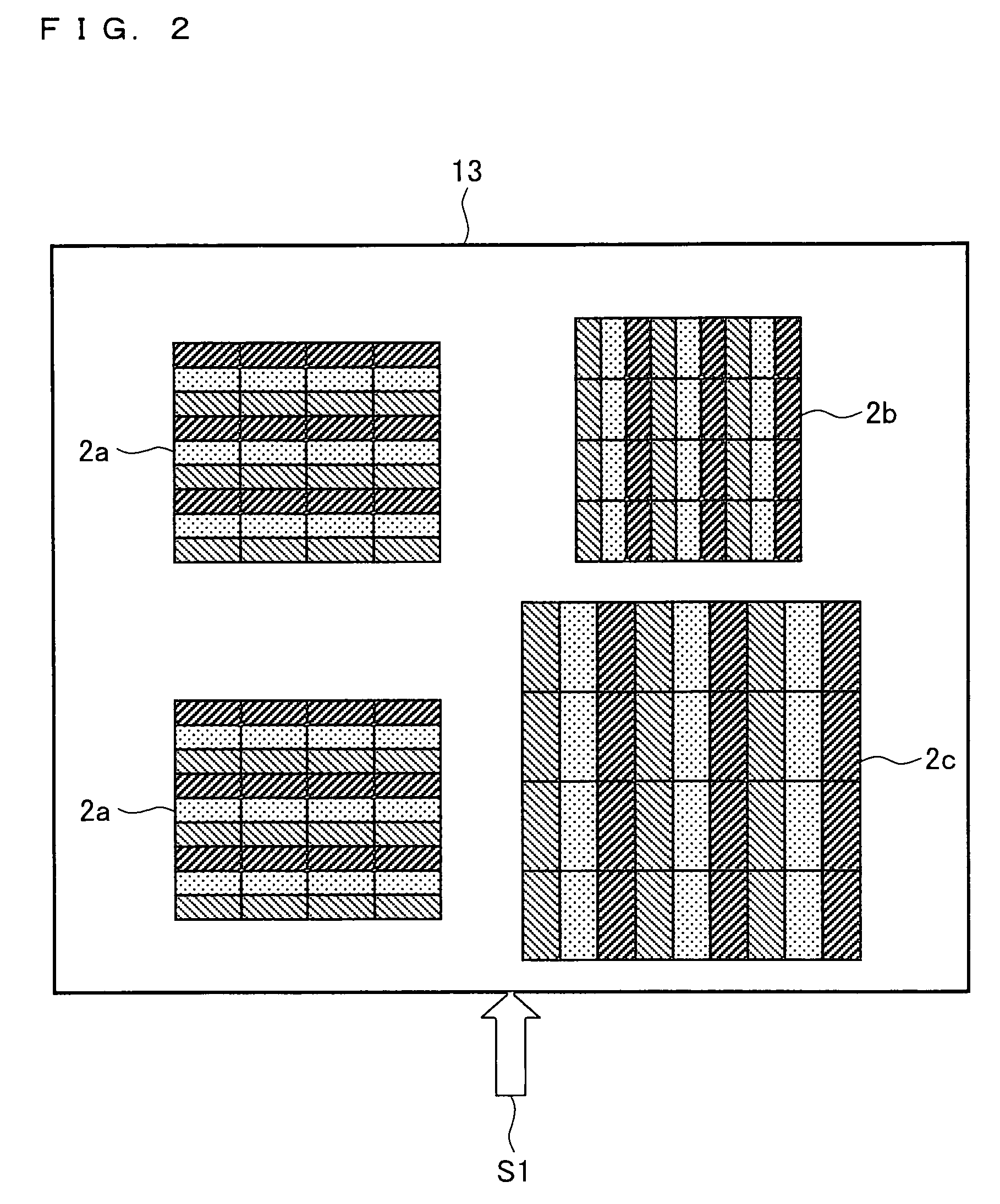
[0042]The following will describe an embodiment of the present invention with reference to FIGS. 1 through 11. The present embodiment presupposes a repair of CF pixels, which is carried out in such a way that defective pixels scattered over a CF panel formed on a substrate which is a medium are filled by discharge by means of inkjet.

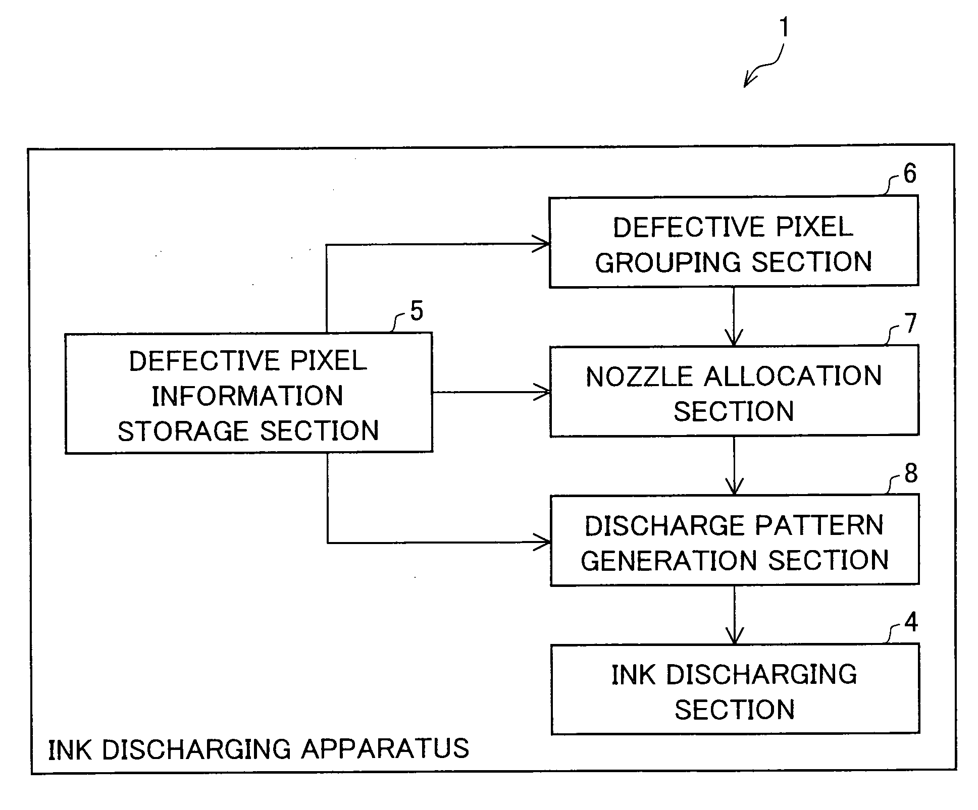
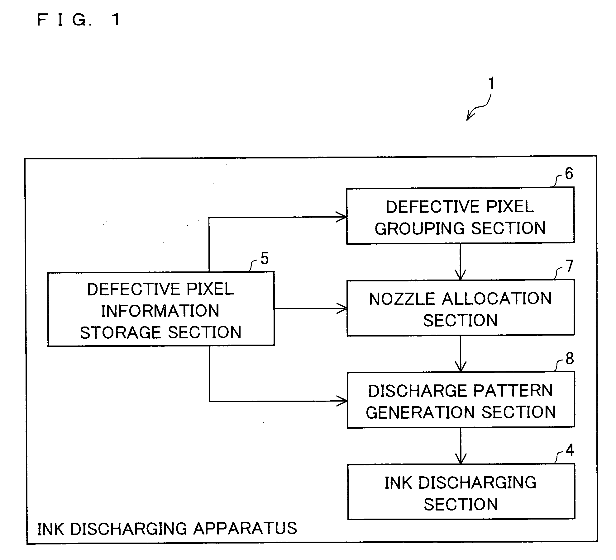
[0043]FIG. 1 relates to the embodiment of the present invention and is a block diagram showing a substantial part of an ink discharging apparatus 1. The ink discharging apparatus 1 includes a defective pixel information storage section 5. The defective pixel information storage section 5 stores information by which defective pixels scattered over a CF panel are specified. The ink discharging apparatus 1 also includes a defective pixel grouping section 6. The defective pixel grouping section 6 generates, based on information which is stored in the defective pixel information storage section 5 and by which defective pixels are specified, defective pixel gr...


PUM


Abstract

The present invention provides an ink discharging apparatus which can reduce processing time required for discharging ink onto all ink discharge targets. The ink discharging apparatus of the present invention has an ink discharging section (4) which is arranged to be able to move relative to a CF panel (2b) in order to discharge ink onto plural defective pixels scattered on the CF panel (2b). The ink discharging section (4) discharges ink onto neighboring defective pixels (3R, 3G, and 3B) among plural defective pixels, by performing a single scanning movement with respect to the neighboring defective pixels (3R, 3G, and 3B).

Description

TECHNICAL FIELD[0001]The present invention relates to an ink discharging apparatus and an ink discharging method, which make it possible to quickly and precisely discharge ink onto an ink discharge target such as a defective pixel.BACKGROUND ART[0002]Ink discharging technologies have recently been not only used for consumer-use printers but also widely used for apparatuses for manufacturing color filter panels (hereinafter, CF panels) of liquid crystal displays and for other manufacturing apparatuses. As such, the use of the technologies has been diversified.[0003]An example of the above is an ink jet patterning technology by which a pattern is formed on a substrate by utilizing the ink discharging technologies. The ink jet patterning technology is a technology to directly print a miniature pattern on a substrate by discharging a small amount of liquid (ink) by an ink discharging apparatus. This ink jet patterning technology has drawn attention as a technology usable in process with...

Claims


Application Information

Patent Timeline
IPC IPC(8): B41J2/135
CPCB41J2/2139G02F1/133514G02F1/1309B41J2202/09
Inventor YOSHIOKA, CHIYOSHI
Owner SHARP KK
Why Eureka
Try Eureka