Image scanner and control method thereof

Active Publication Date: 2009-05-14
RISO KAGAKU CORP
View PDF5 Cites 9 Cited by
  • Summary
  • Abstract
  • Description
  • Claims
  • Application Information

AI Technical Summary

Benefits of technology

[0027]The foregoing configuration is capable of shortening the time required for the image scanner to become ready for the ori

Problems solved by technology

This deteriorates the usab

Method used


Image

  • Image scanner and control method thereof
  • Image scanner and control method thereof
  • Image scanner and control method thereof

Examples


Embodiment Construction

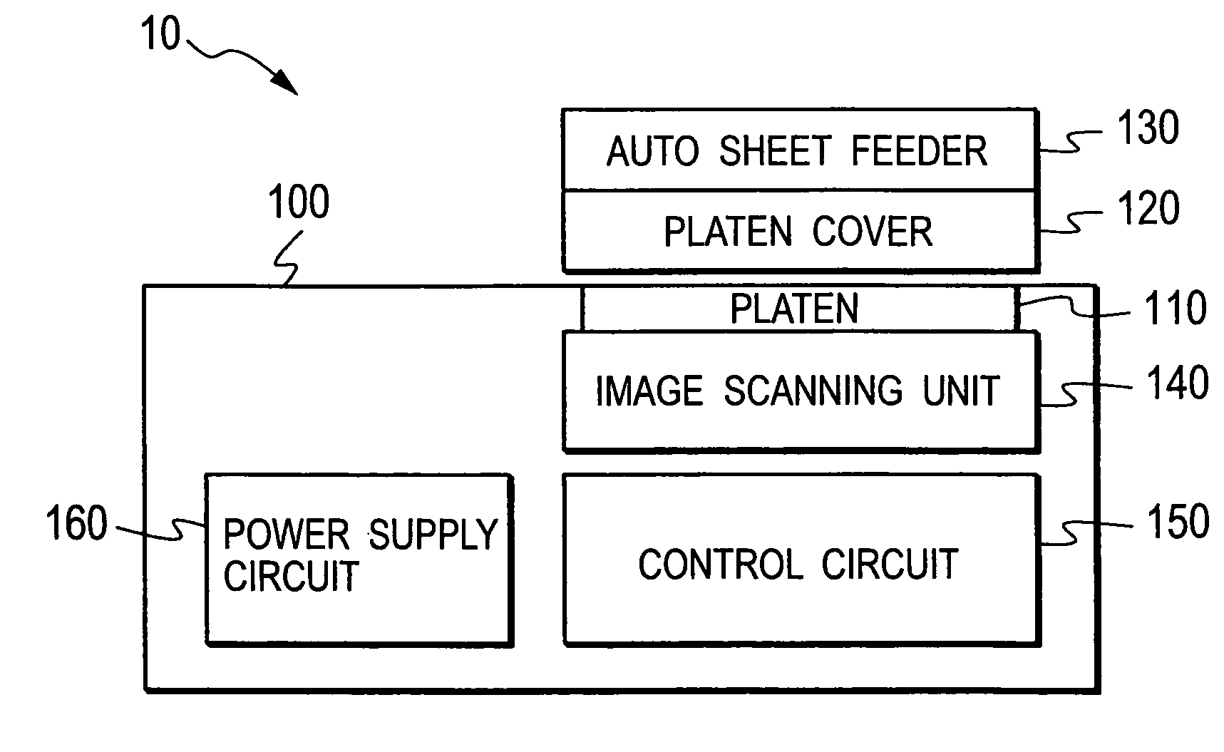
[0034]Descriptions will be provided hereinbelow for the embodiment of the present invention on the basis of the drawings. While the following drawings are described, the same or similar components are denoted by the same or similar reference numerals. FIG. 2 is a block diagram showing a schematic configuration of an image scanner 10 according to the present embodiment. The image scanner 10 employs a flat-bed system in which an original is fixed to be scanned. The image scanner 10 includes: a scanner main body 100 including a platen 110 on which to place an original; a platen cover 120 configured to cover the platen 110; and an auto sheet feeder 130 integrated with the platen cover 120 and configured to automatically feed an original to the platen 110. Examples representing the image scanner 10 include a scanner apparatus, a copier, a facsimile machine and a multi-functional printer. The present invention is applicable to these machines, but not limited to these machines.

[0035]The sc...


PUM


Abstract

An image scanner operates in a normal mode in which an image scanning process is executable; and a power saving mode in which less electric power is consumed than in the normal mode. The image scanner includes: a CPU for switching the image scanner between the normal mode and the power saving mode; an original size sensor circuit; and an FPGA connected to the CPU and the original size sensor circuit. In the normal mode, the CPU configures, in the FPGA, a normal-mode circuit needed for the image scanning process. When the image scanner transfers from the normal mode to the power saving mode, the CPU configures, in the FPGA, a power-saving-mode circuit for communicating with the original size sensor circuit, and stops the original size sensor circuit from operating. The power-saving-mode circuit is smaller in circuit size than the normal-mode circuit.

Description

CROSS REFERENCE TO RELATED APPLICATION[0001]This application is based upon and claims the benefit of priority from the prior Japanese Patent Application No. 2007-295378, filed on Nov. 14, 2007, the entire contents of which are incorporated herein by reference.BACKGROUND OF THE INVENTION[0002]1. Field of the Invention[0003]The present invention relates to an image scanner and a control method thereof. Particularly, the present invention relates to an image scanner which includes a power saving function, and which is capable of quickly performing necessary processes when the image scanner is returned to a normal mode from a power saving mode, as well as a method of controlling the image scanner.[0004]2. Description of the Related Art[0005]Recently, power saving in image scanners has been promoted, as in the disclosure in Japanese Unexamined Patent Publication No. 2007-060211. Therefore, commonly used are image scanners having a power saving mode in which less power is consumed than in...

Claims


Application Information

Patent Timeline
IPC IPC(8): H04N1/04
CPCH04N1/00708H04N1/00782H04N1/00885H04N2201/0422H04N1/00928H04N2201/0081H04N1/00896
Inventor HIRAI, MASATO
Owner RISO KAGAKU CORP
Why Eureka
Try Eureka