Stereoscopic imaging device

Inactive Publication Date: 2009-05-14
FUJIFILM CORP
View PDF2 Cites 42 Cited by
  • Summary
  • Abstract
  • Description
  • Claims
  • Application Information

AI Technical Summary

Benefits of technology

[0018]The present invention can provide a stereoscopic imaging device which ha

Problems solved by technology

Thus, the configuration of FIG. 7 is extremely large in the depth direction as compared with typical compact digital cameras, causing poor portability.
Further, as the longitudinal size of the camera body is reduced when the lens barrels are disposed along the depth direction, a monitor su

Method used


Image

  • Stereoscopic imaging device
  • Stereoscopic imaging device
  • Stereoscopic imaging device

Examples


Embodiment Construction

[0027]A preferred embodiment for implementing a stereoscopic imaging device according to the present invention will now be described in accordance with the accompanying drawings.

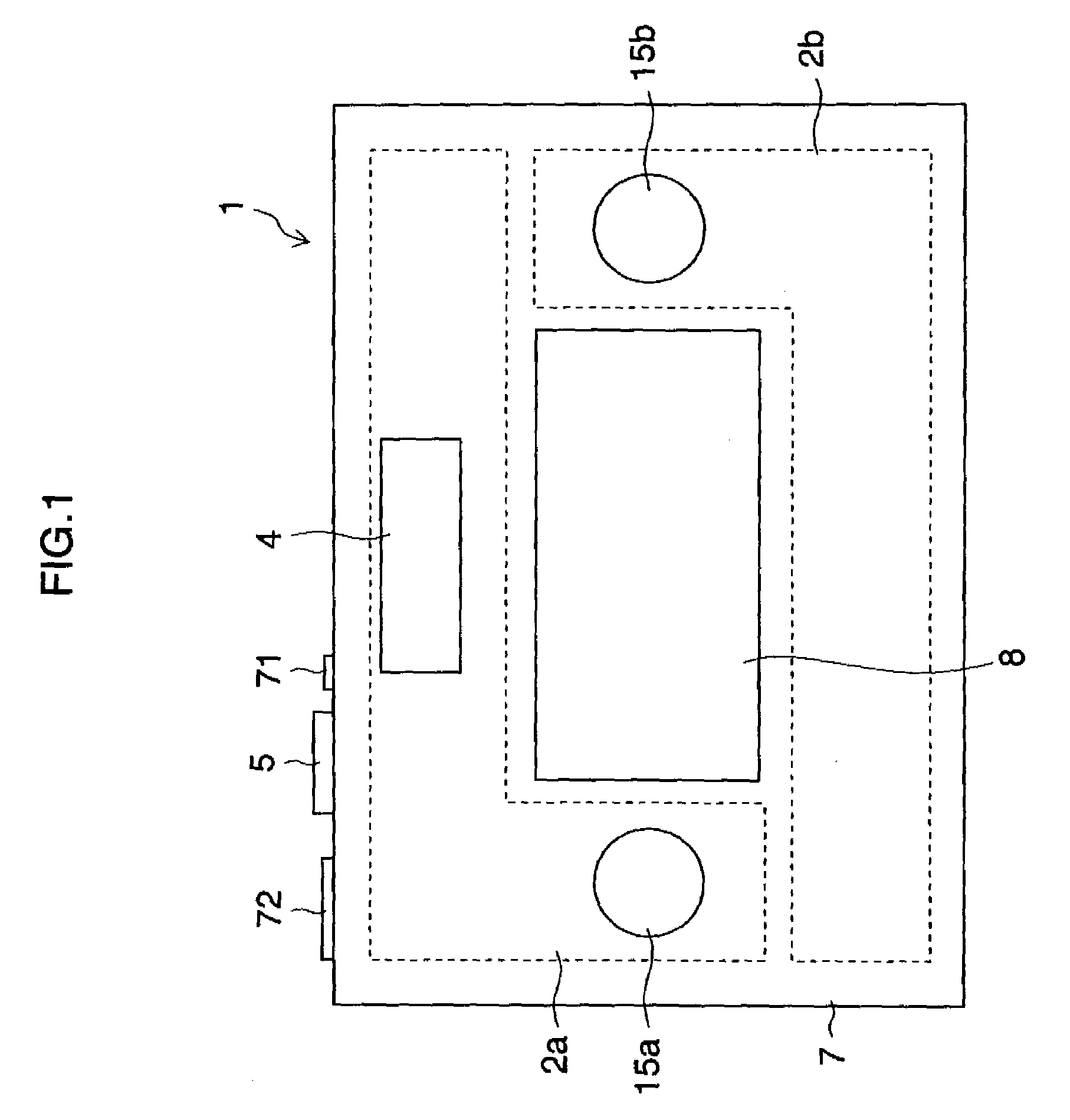
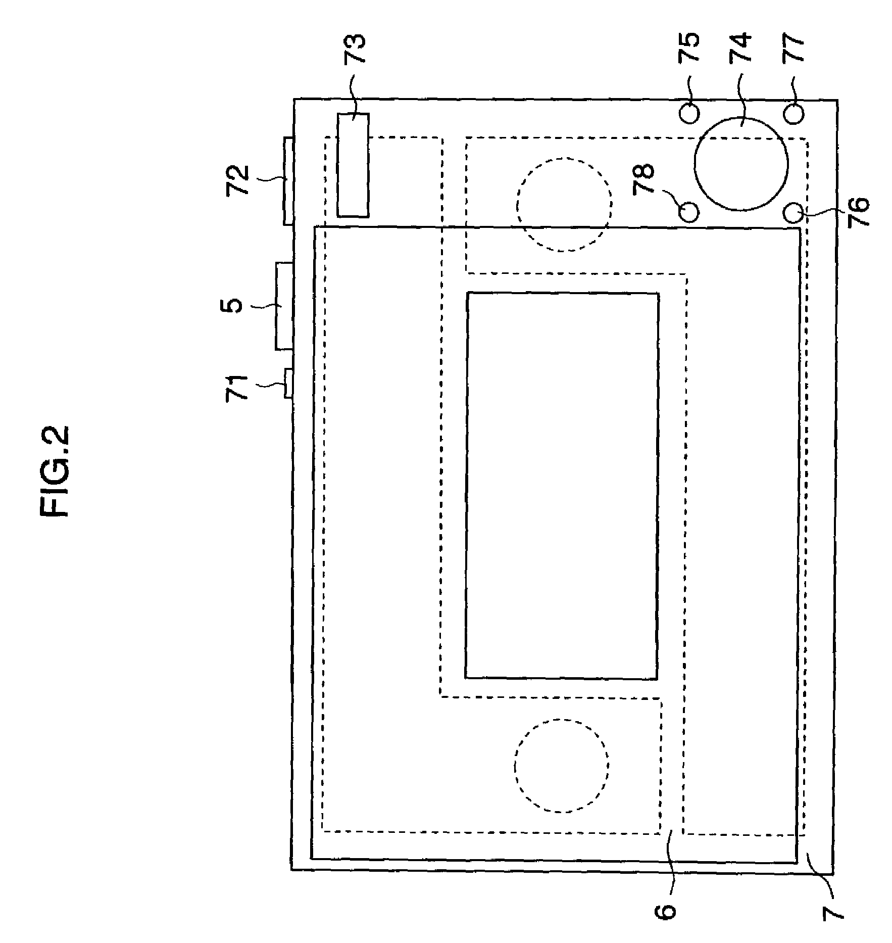
[0028]FIG. 1 is a plan view showing a compound-eye digital camera 1. FIG. 2 is a rear view showing the compound-eye digital camera 1.

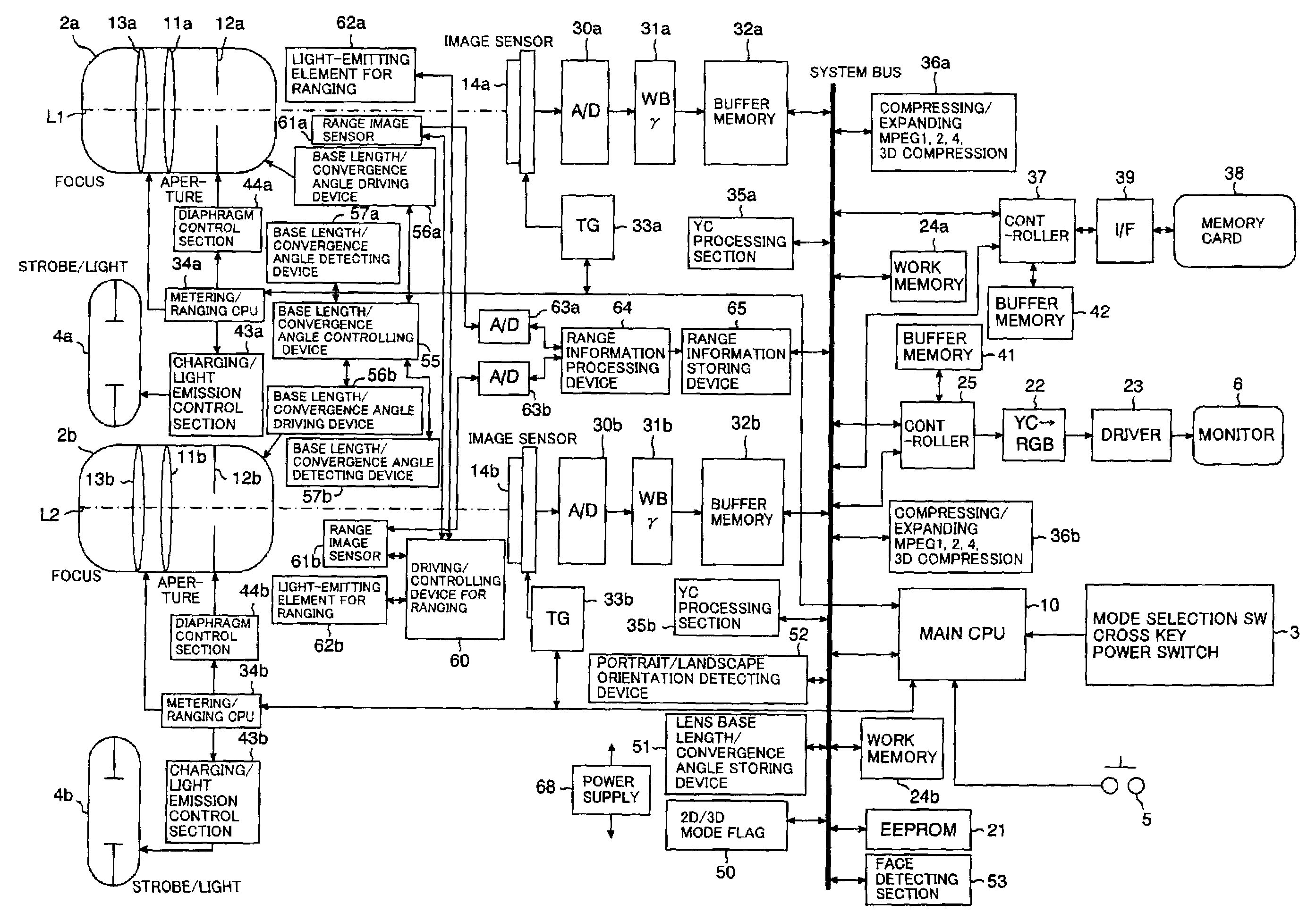
[0029]The compound-eye digital camera 1 includes a plurality of imaging systems (two imaging systems in FIG. 1) and can photograph a stereoscopic image of the same subject viewed from a plurality of points (two points on the right and left in FIG. 1).

[0030]A camera body 7 of the compound-eye digital camera 1 is substantially shaped like a rectangular solid. As shown in FIG. 1, the front side of the camera body 7 mainly includes a first objective lens 15a of a first imaging system 2a, a second objective lens 15b of a second imaging system 2b, a strobe 4, and a battery cover 8 which can be opened and closed. The inner side of the battery cover 8 includes a battery case for storin...


PUM


Abstract

A compound-eye camera comprises: a camera body substantially shaped like a rectangular solid having a front side and a back side larger than other sides and including a display device on the back side; and substantially L-shaped first and second lens barrels, each storing a refractive optical system including two reflective optical elements for refracting a photographing optical axis twice, the lens barrels guiding subject images incident on a pair of right and left objective lenses to image sensors. In the camera, the substantially L-shaped first and second lens barrels are each disposed along two adjacent inner surfaces of the camera body. Thereby, a compound-eye camera which has excellent portability and enables the installation of a large display device is achieved.

Description

BACKGROUND OF THE INVENTION[0001]1. Field of the Invention[0002]The present invention relates to a stereoscopic imaging device and particularly relates to a stereoscopic imaging device which can photograph an image enabling a stereoscopic view (three-dimensional image).[0003]2. Description of the Related Art[0004]Japanese Patent Application Laid-Open No. 2002-112288 describes a stereoscopic photographing optical unit having a variable base length.[0005]Japanese Patent Application Laid-Open No. 8-304943 describes a stereoscopic photographing device which integrally holds a pair of movable lenses for right and left eyes and includes a support mechanism provided at the center of the pair of right and left movable lenses to support the movable lenses movably along the optical axis.[0006]Japanese Patent Application Laid-Open No. 7-152096 describes a compound-eye imaging system which is made up of a plurality of lens pairs obtained by integrally molding a plurality of lenses having the sa...

Claims


Application Information

Patent Timeline
IPC IPC(8): G03B35/00H04N13/239
CPCG03B35/00H04N2213/001H04N13/0239H04N13/239
Inventor MAEZONO, NOBUYOSHI
Owner FUJIFILM CORP
Why Eureka
Try Eureka