Eureka AIR delivers breakthrough ideas for toughest innovation challenges, trusted by R&D personnel around the world.

Image forming apparatus

Inactive Publication Date: 2009-05-14
SHARP KK
View PDF21 Cites 12 Cited by
  • Summary
  • Abstract
  • Description
  • Claims
  • Application Information

AI Technical Summary

Benefits of technology

[0009]In view of the circumstances described above, it is therefore an object of the present invention to provide an image forming apparatus which can be formed with a duct mechanism for exhausting ozone without making the apparatus larger.
[0010]It is another object of the present invention to provide a color image forming apparatus including a duct mechanism that can exhaust air from a plurality of chargers through a common duct so as to achieve efficient space usage inside the apparatus.
[0016]Also, even when a plurality of photoreceptors and charges are included as in a color image forming apparatus, it is possible to exhaust air using a single common duct. Accordingly, it is possible to provide a duct mechanism which can achieve efficient space usage.
[0017]Further, since the moving mechanism for setting and releasing the photoreceptor positioning member with respect to the photoreceptor is provided, it is possible to mount and dismount the photoreceptor in a simple manner by moving together the photoreceptor positioning member and the duct part integrated with it.

Problems solved by technology

If high-concentration ozone and NOx stagnate inside the image forming apparatus and produce oxides on the photoreceptor surface, the surface resistance of the photoreceptor lowers, deteriorating the resolution of the electrostatic latent image and causing image degradation in the electrostatic latent image, called “image flowing”.
The oxides thus formed on the photoreceptor surface will cause remarkable reduction in electric resistance under high humidity environment and produce serious image degradation in the printed result.
Further, this also causes deterioration of other components than the photoreceptor, shortening the life of the image forming apparatus itself.
Such products exhibit high resistance under low-humidity environment; in particular, when they adhere to a corona discharging electrode, grid electrode or the like, they are prone to cause charging unevenness.
However, in the image forming apparatus such as a color image forming apparatus that includes a plurality of photoreceptor drums and chargers, a separate duct needs to be provided for each image forming unit, hence the final structure will become complicated and also cause difficulties in making the apparatus compact.

Method used


Image

  • Image forming apparatus
  • Image forming apparatus
  • Image forming apparatus

Examples


first embodiment

The First Embodiment

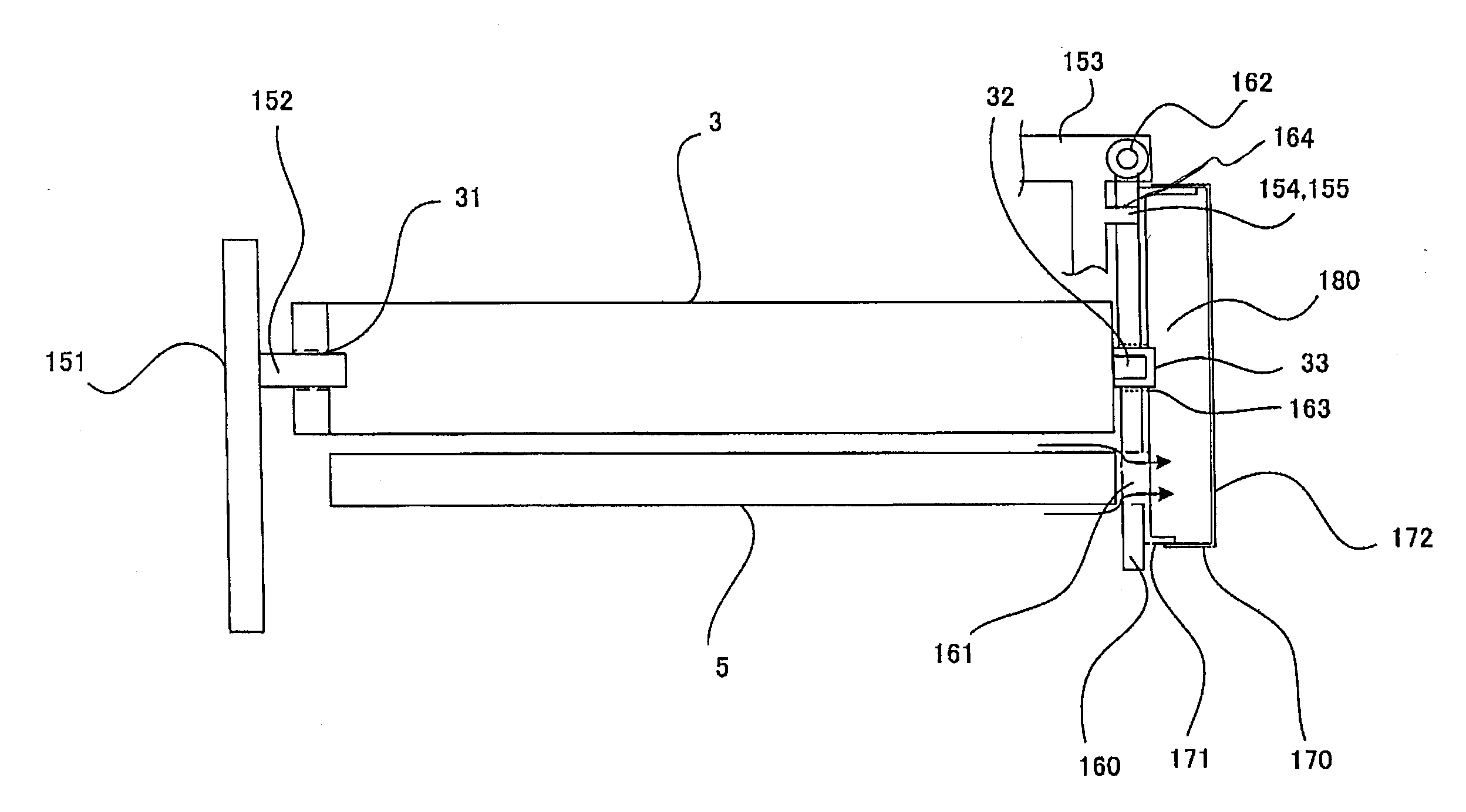
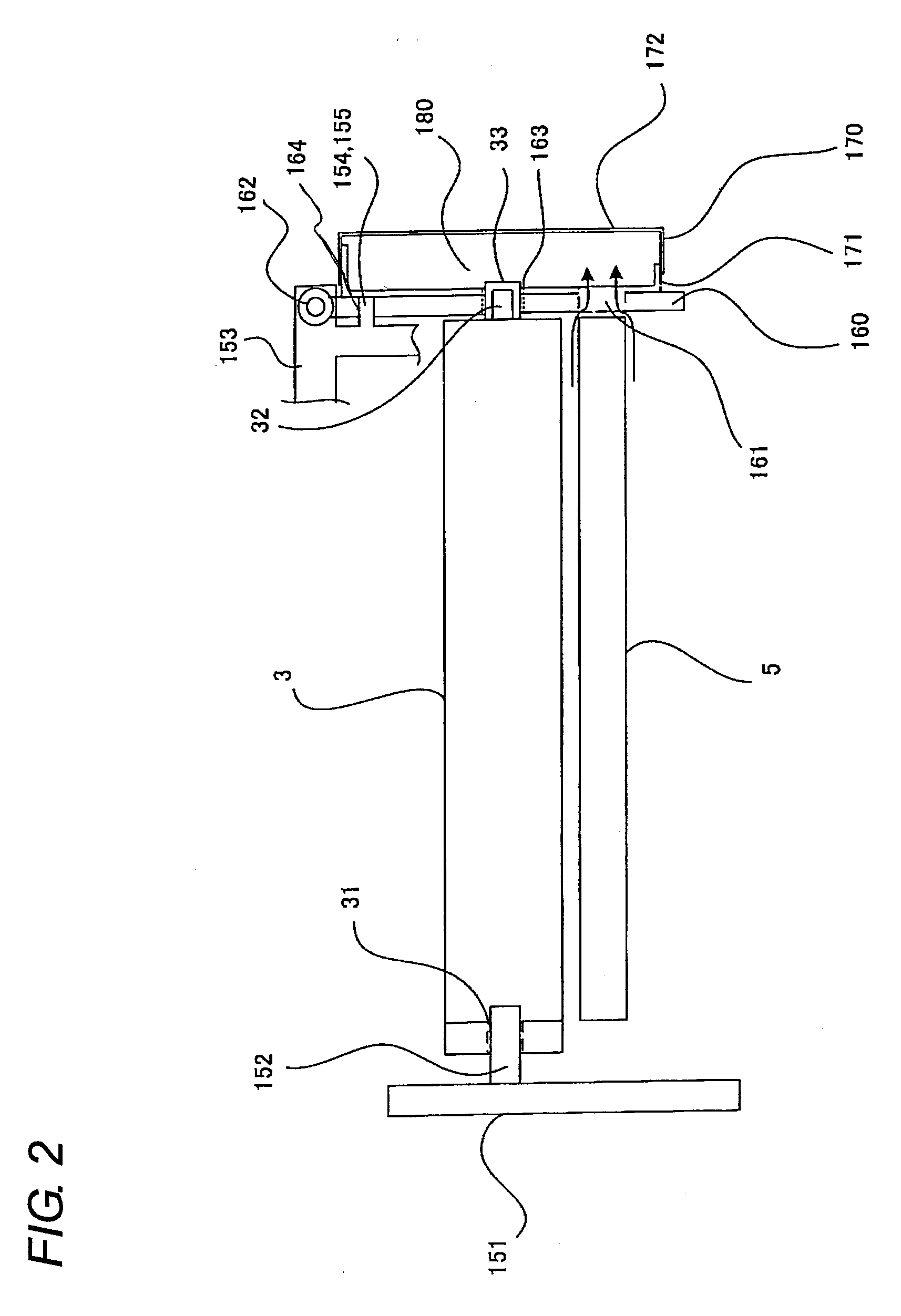
[0050]FIG. 2 is a sectional view showing an exhaust mechanism for the image forming apparatus in the first embodiment. FIGS. 3, 4 and 5 are perspective views showing the exhaust mechanism of the image forming apparatus in the first embodiment. FIG. 3 is a perspective view showing a state in which all the covers are removed. FIG. 4 is a view showing a state in which a cover 171 is attached. FIG. 5 is a view showing a state in which all covers are attached to the image forming apparatus.

[0051]Photoreceptor 3 is positioned, by a photoreceptor positioning shaft 152 arranged on a backside frame 151 of the main apparatus body, and by a photoreceptor drum positioning member 160 on the front side of the main apparatus body. Formed on the backside end of photoreceptor 3 is a positioning hole 31, into which photoreceptor positioning shaft 152 is inserted to position the photoreceptor. On the front side end of photoreceptor 3, a rotary shaft 32 and a bearing around it are a...

second embodiment

The Second Embodiment

[0058]The cover as a duct part may be integrally formed with the external housing front cover of the main apparatus body. FIGS. 7 and 8 are sectional views showing an exhaust mechanism in an image forming apparatus of the second embodiment. FIG. 7 shows an example in which a cover 173 is integrally formed with a front cover 190 of the main apparatus body. This arrangement makes it possible to reduce parts in number. FIG. 8 shows a state in which front cover 190 is opened in the example where cover 173 is integrally formed with front cover 190 of the main apparatus body.

[0059]Cover 173 as a duct part is integrally formed with front cover 190 as the exterior housing of the main apparatus body. Cover 173 is formed so that its enclosing wall is bent vertically to front cover 190. Front cover 190 has a pivot shaft 191 formed therewith, which is rotatably supported by main body front frame 153.

[0060]When front cover 190 is closed, the enclosing wall of cover 171 and t...


PUM


Abstract

A photoreceptor 3 is positioned by a photoreceptor positioning member 152 arranged on a backside frame 151 of the main apparatus body and by a photoreceptor drum positioning member 160 on the front side of the main apparatus body. Photoreceptor positioning member 160 formed of metal is united with resinous covers 171 and 172 as duct parts. Each of covers 171 and 172 has an enclosing wall that is bent vertically with respect to its bottom along the outline, so that the enclosing wall of cover 171 and the enclosing wall of cover 172 fit each other, forming a duct 180 therein. Duct 180 is arranged to communicate with a charger 5 via an opening 161 formed in photoreceptor positioning member 160 and cover 171.

Description

[0001]This Nonprovisional application claims priority under 35 U.S.C. §119(a) on Patent Application No. 2007-294026 filed in Japan on 13 Nov. 2007, the entire contents of which are hereby incorporated by reference.BACKGROUND OF THE INVENTION[0002](1) Field of the Invention[0003]The present invention relates to an image forming apparatus including a duct mechanism for exhausting ozone, nitrogen oxides (NOx) that arise from a charger for electrifying a photoreceptor at a predetermined potential in a copier, printer, facsimile machine or the like.[0004](2) Description of the Prior Art[0005]In image forming apparatus using an electrophotographic image forming process, a charger is used to uniformly electrify the photoreceptor surface at a predetermined potential. Since this charger electrifies the photoreceptor using corona discharge, ozone and nitrogen oxides (NOx) arise as byproducts during discharging. If high-concentration ozone and NOx stagnate inside the image forming apparatus an...

Claims


Application Information

Patent Timeline
IPC IPC(8): G03G21/20
CPCG03G21/206
Inventor KADOWAKI, HIDEAKI
Owner SHARP KK
Why Eureka
Eureka Blog
Learn More