Endoscope device
- Summary
- Abstract
- Description
- Claims
- Application Information
AI Technical Summary
Benefits of technology
Problems solved by technology
Method used
Image

Examples
embodiment 1
[0032]Incision forceps in a first embodiment of the present invention are described below with reference to the drawings.
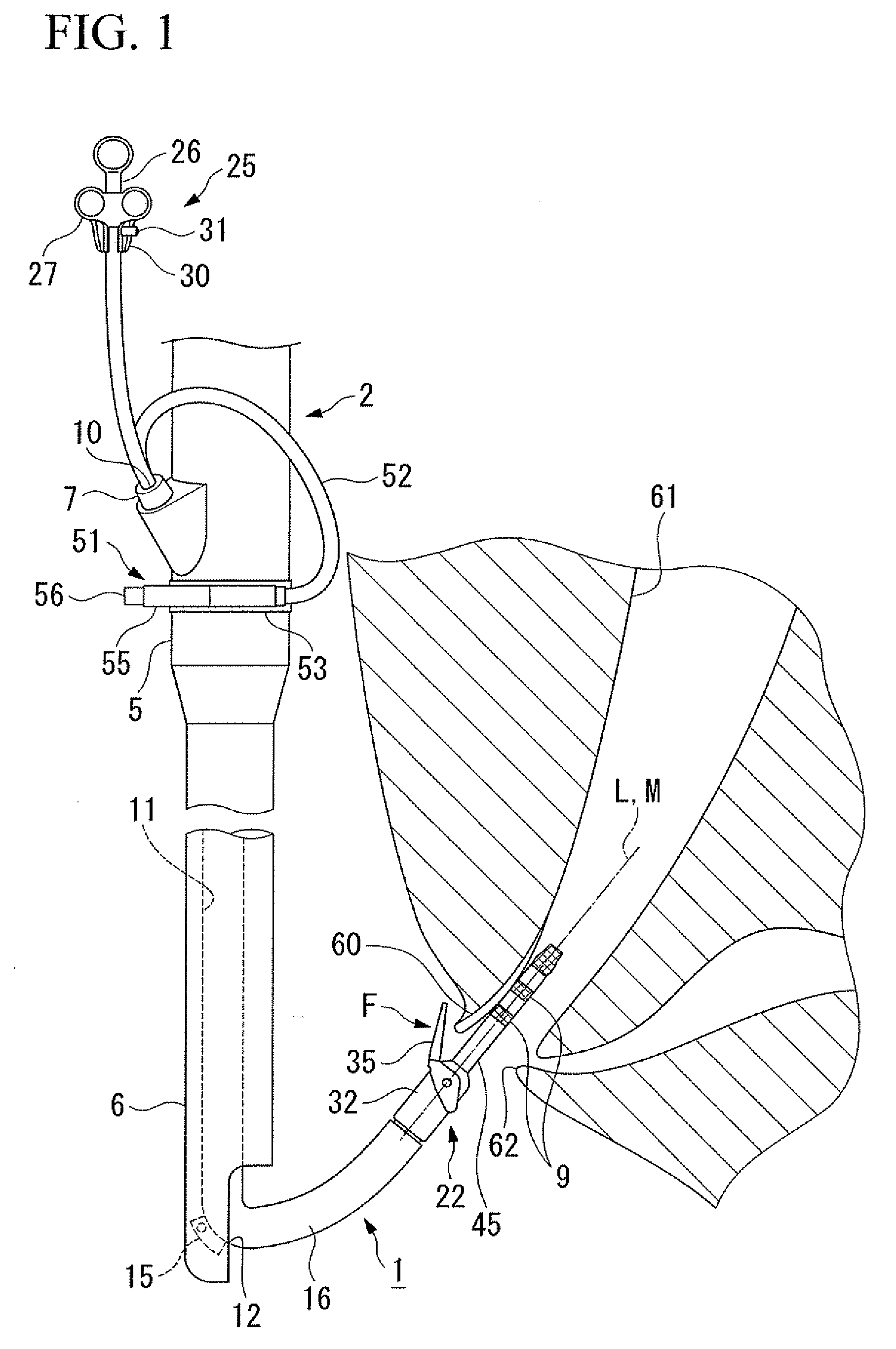
[0033]As shown in FIG. 1, an incision forceps 1 in the present invention performs treatment by being used with an endoscope 2.
[0034]Therefore, the endoscope 2 that is used with the incision forceps 1 shall first be described.
[0035]The main constituent elements of the endoscope 2 are an endoscope operation portion 5 that the operator holds in his hand and performs various operations, and an endoscope insertion portion 6 that is inserted into a body cavity. That is, the endoscope 2 is constituted by the endoscope operation portion 5 being attached to the proximal side end of the endoscope insertion portion 6 that is hollow and elongated.
[0036]A forceps plug 7 for inserting various tools is provided in the endoscope operation portion 5. A forceps plug opening portion 10 that serves as the insertion opening for various treatment tools is formed in the forceps plug 7.
[...
embodiment 2
[0064]Next, the second embodiment of the present invention shall be described.
[0065]FIG. 7 to FIG. 11 show the second embodiment of the present invention.
[0066]In FIG. 7 to FIG. 11, portions identical to constituent elements disclosed in FIG. 1 to FIG. 6 shall be assigned the same reference numerals and explanations thereof shall be omitted here.
[0067]The basic constitution of this embodiment is identical to the first embodiment, and so only the points of difference shall be given here.
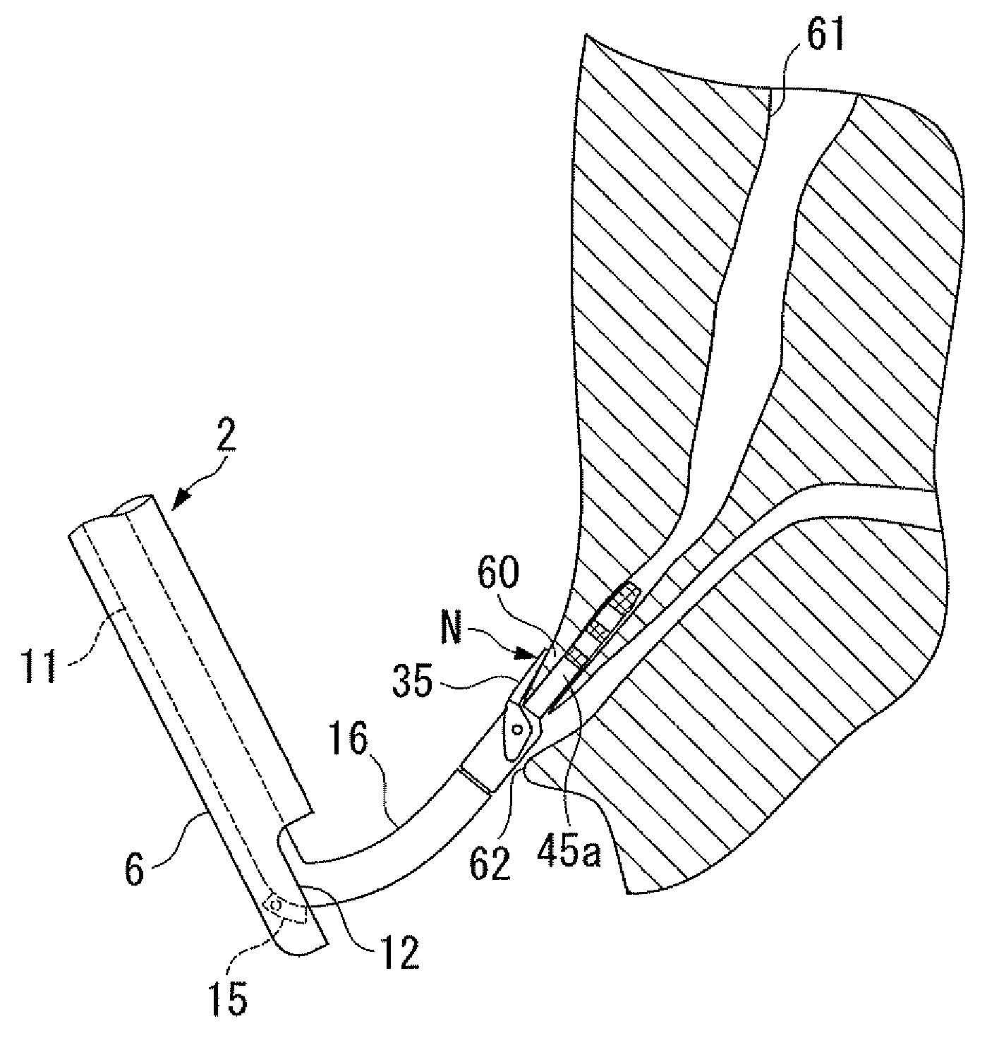
[0068]In the present embodiment, as shown in FIG. 7, an opening portion is formed at the distal end of the distal end cover 32, and this opening portion is opened wide. That is, the opening portion of the distal end cover 32 serves as a distal end opening portion 65 of the lumen 47. On the other hand, as shown in FIG. 8, the injection opening portion 56 of the forceps attachment portion 51 serves as a rear end opening portion.
[0069]Also, a guide tube 45a is formed to be longer than the guide tube 45 i...
embodiment 3
[0072]Next, the third embodiment of the present invention shall be described.
[0073]FIG. 12 shows the third embodiment of the present invention.
[0074]In the present embodiment, a guide tube 45b is attached at the distal end of the distal end cover 32 to be rotatable about the axial lines L and M with respect to the sheath portion 16 and the forceps piece 35. That is, a flange portion 66 is provided at the base end portion of the attachment cylinder portion 46a, and this flange portion 66 functions as a retaining portion of the attachment cylinder portion 46a from the distal end cover 32. The attachment cylinder portion 46a is rotatable about the axial line L, and the guide tube 45b is attached to this attachment cylinder portion 46a.
[0075]With this kind of constitution, when the coil tube 17 is rotated in the state of the guide tube 45b being inserted in the papilla opening portion 62, the forceps piece 35 rotates about the axial lines L and M with the guide tube 45b remaining stati...
PUM
 Abstract
Description
Claims
Application Information
 - R&D Engineer
- R&D Manager
- IP Professional
- Industry Leading Data Capabilities
- Powerful AI technology
- Patent DNA Extraction
Browse by: Latest US Patents, China's latest patents, Technical Efficacy Thesaurus, Application Domain, Technology Topic.
© 2024 PatSnap. All rights reserved.Legal|Privacy policy|Modern Slavery Act Transparency Statement|Sitemap