Wall liner

Inactive Publication Date: 2009-05-21
WORTHINGTON ARMSTRONG VENTURE
View PDF21 Cites 12 Cited by
  • Summary
  • Abstract
  • Description
  • Claims
  • Application Information

AI Technical Summary

Benefits of technology

[0013]The invention uses the above-described T-beams of the prior art as vertical stiffeners for wallboard sheets that form a vertical wall liner, so that the wallboard can stand vertically alone. Even though such a T-beam has virtually no strength as a column, the invention enables such a beam to satisfactorily reinforce wallboard formed into a liner, so the wallboard can stand alone to form the wall. Wallboard

Problems solved by technology

Wallboard sheets, generally formed of gypsum between outer paper layers, ar

Method used


Image

  • Wall liner
  • Wall liner
  • Wall liner

Examples


first embodiment

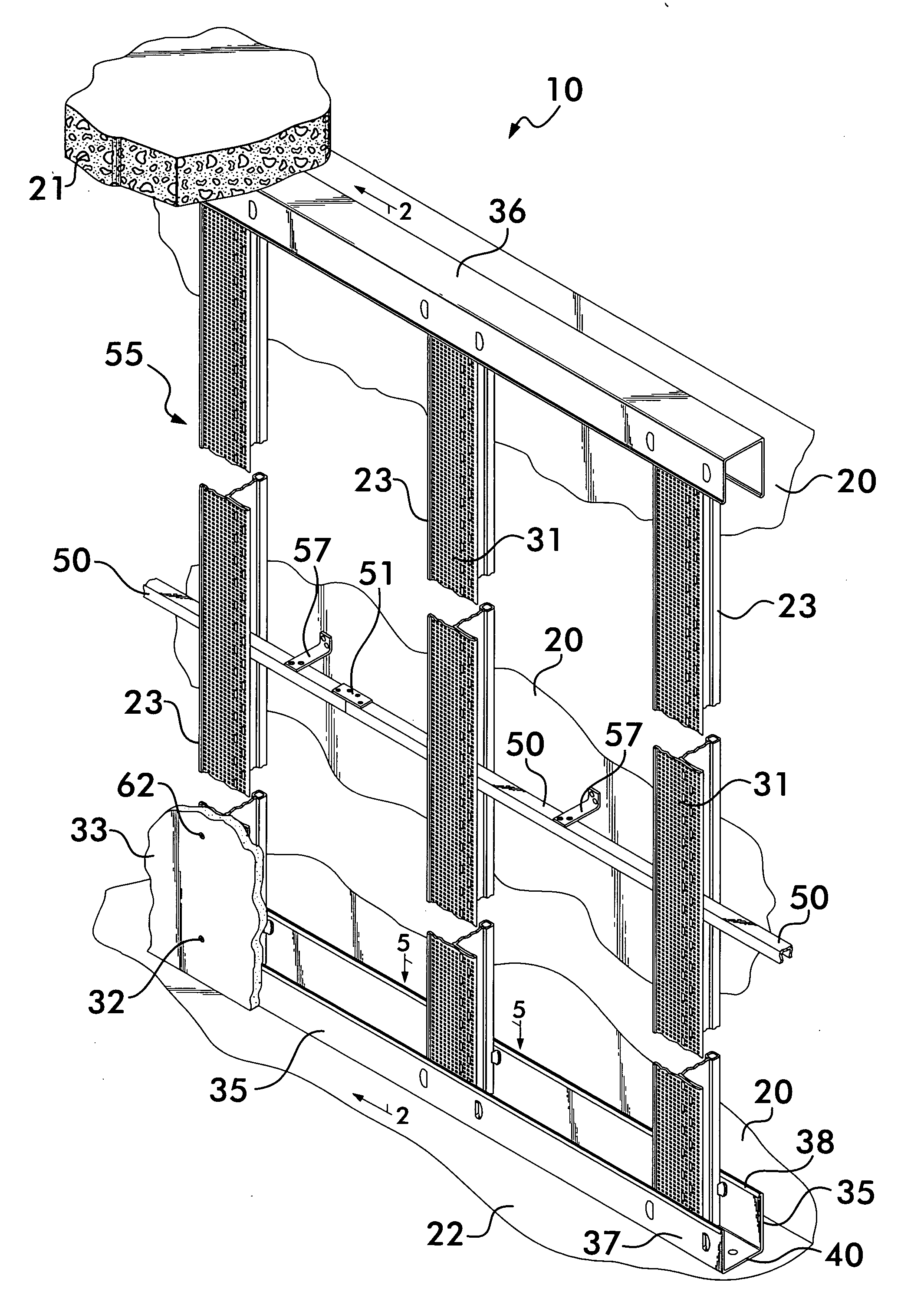
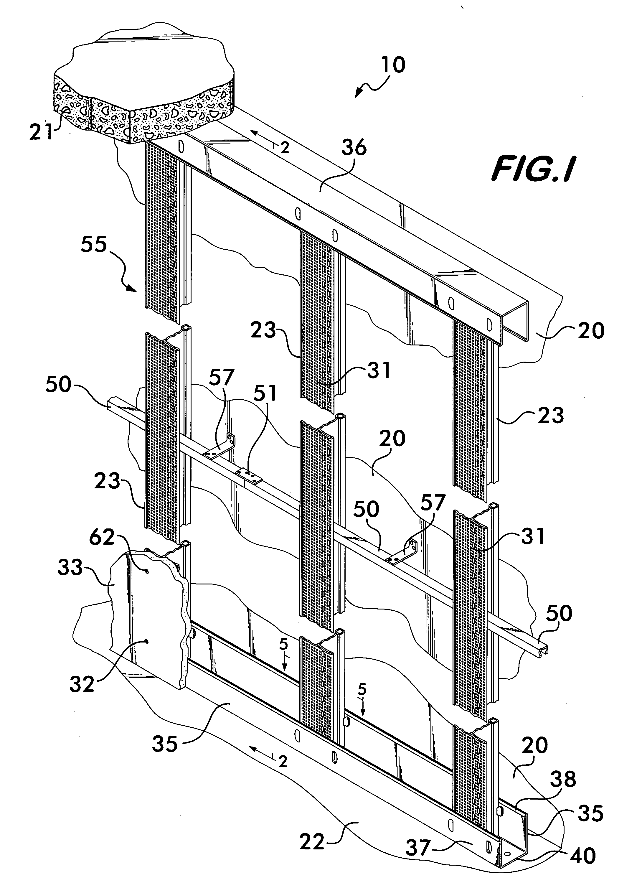
[0050]In the invention disclosed herein, the T-beam vertical stiffeners 23 have openings 42 spaced vertically in the webs26. The openings 42 have a larger upper portion 45, which is roughly rectangular, and a smaller bottom portion 46, which is U-shaped.

[0051]A strut 50 having a U-shaped cross section corresponding to the shape of the lower portion 46 of opening 42, that has been maneuvered through the larger opening 45, engages the bottom portion 46 in a force fit, as shown particularly in FIGS. 2, 7 and 7A. The struts 50 may be spliced together longitudinally with a splice plate 51, using pre-tapped holes in the strut 50 and plate 51.

[0052]The strut 50, which in the embodiment shown, has a cross section of an inverted U, reinforces each of the T-beam vertical stiffeners 23, from back wall 20.

[0053]Angle shaped brackets 57, spaced along strut 50, are anchored into back wall 20 with suitable fasteners, such as hardened nails 61, and are secured to strut 50 by screws 62. The brackets...

second embodiment

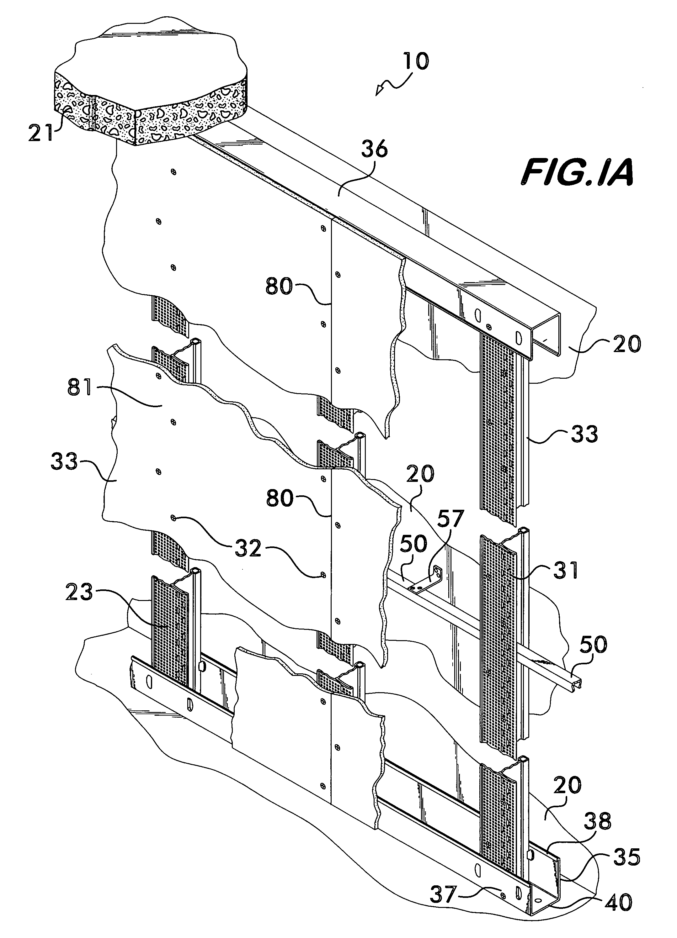
[0054]In the invention disclosed herein, struts 50 are not used, so that the T-beam vertical stiffeners 23 are not tied together, except at the top track 36 and bottom track 35, where they engage the tracks. Brackets 70 tie an individual T-beam vertical stiffener 23 to the structural wall 20 in back of the wall liner 10, at any desired vertical location on the T-beam vertical stiffener 23. The bracket 70 is L-shaped and has a first longer leg 71 and a second shorter leg 72.

[0055]An example of leg length may be 4% inches for the longer leg 71, and 1½ inches for the shorter leg 72. The legs 71 and 72 have holes 75 spaced in the legs at desired locations which provide for adjustability of the bracket 70. Where a structural back wall 20 varies in contour, a bracket 70 is adjusted to provide a solid connection between the structural back wall 20, and the T-beam vertical stiffener 23.

[0056]Examples of such adjustability are shown in FIG. 8, where in views (a) and (b), the shorter leg 72 e...


PUM


Abstract

Rolled T-beams of the kind used in suspended ceilings, act as vertical stiffeners in a wall liner for a back wall. The vertical stiffeners, reinforced from the back wall, keep the sheets of wallboard that form the wall liner vertically aligned and together. The weight of the wallboard liner is borne directly by the floor under the liner, without support by columns or studs.

Description

[0001]This application is a continuation-in-part of prior application Ser. No. 11 / 985,690, filed Nov. 15, 2007, for Wall Liner.BACKGROUND OF THE INVENTION[0002]1. Field of the Invention[0003]This invention is in the field of vertical liners for a back wall, such as a foundation wall. A liner is formed of adjacent sheets of wallboard extending in a vertical plane in front of a back wall. Such a liner presents a pleasing appearance to a viewer, and also serves to insulate a space against temperature extremes, noise, and humidity.[0004]2. Prior Art[0005]a) Vertical Wall Liners[0006]Prior art, vertical wall liners are formed by affixing sheets of wallboard to structural columns, or studs, of wood, or of metal having a U-shaped cross section with a leg of the U extending parallel to the plane of the wall. Nails, or screws, affix the sheets to the studs. Such studs, acting as columns, bear virtually all the weight of the wallboard, and are subject to twisting and buckling from such load, ...

Claims


Application Information

Patent Timeline
IPC IPC(8): E04B2/56E04G11/06E04B2/72
CPCE04B1/0007E04B1/7675E04F13/0807E04C2003/046E04C3/07
Inventor SAREYKA, BRETT W.HEATH, WILLIAM L.PLATT, WILLIAM J.
Owner WORTHINGTON ARMSTRONG VENTURE
Why Eureka
Try Eureka