Supercharge Your Innovation With Domain-Expert AI Agents!

System and method for supplying processing water

a technology of processing water and system, applied in the direction of filtration separation, separation process, manufacturing tools, etc., can solve the problems of system requirements, system requiring additional effort, and pipe system liable to be clogged with abrasive,

Inactive Publication Date: 2009-05-21
TOWA
View PDF4 Cites 4 Cited by
  • Summary
  • Abstract
  • Description
  • Claims
  • Application Information

AI Technical Summary

Benefits of technology

[0008]The numerals in parenthesis used in the description of “MEANS FOR SOLVING THE PROBLEMS”, “EFFECTS OF THE INVENTION” and “BEST MODE FOR CARRYING OUT THE INVENTION” are intended for facilitating the comparison between the terms used in the description and the components shown in the drawings. The use of these numerals should never be understood to mean that “the meaning of the terms used in the description should be restricted to the components shown in the drawings.”

Problems solved by technology

Therefore, the pipe system is liable to be clogged with the abrasive.
Secondly, the clarifying filter is also likely to be clogged with the abrasive, chips or other materials.
To deal with these problems, the system requires additional effort for the management and maintenance of the pipe system and clarifying filter.

Method used


Image

  • System and method for supplying processing water
  • System and method for supplying processing water
  • System and method for supplying processing water

Examples


first embodiment

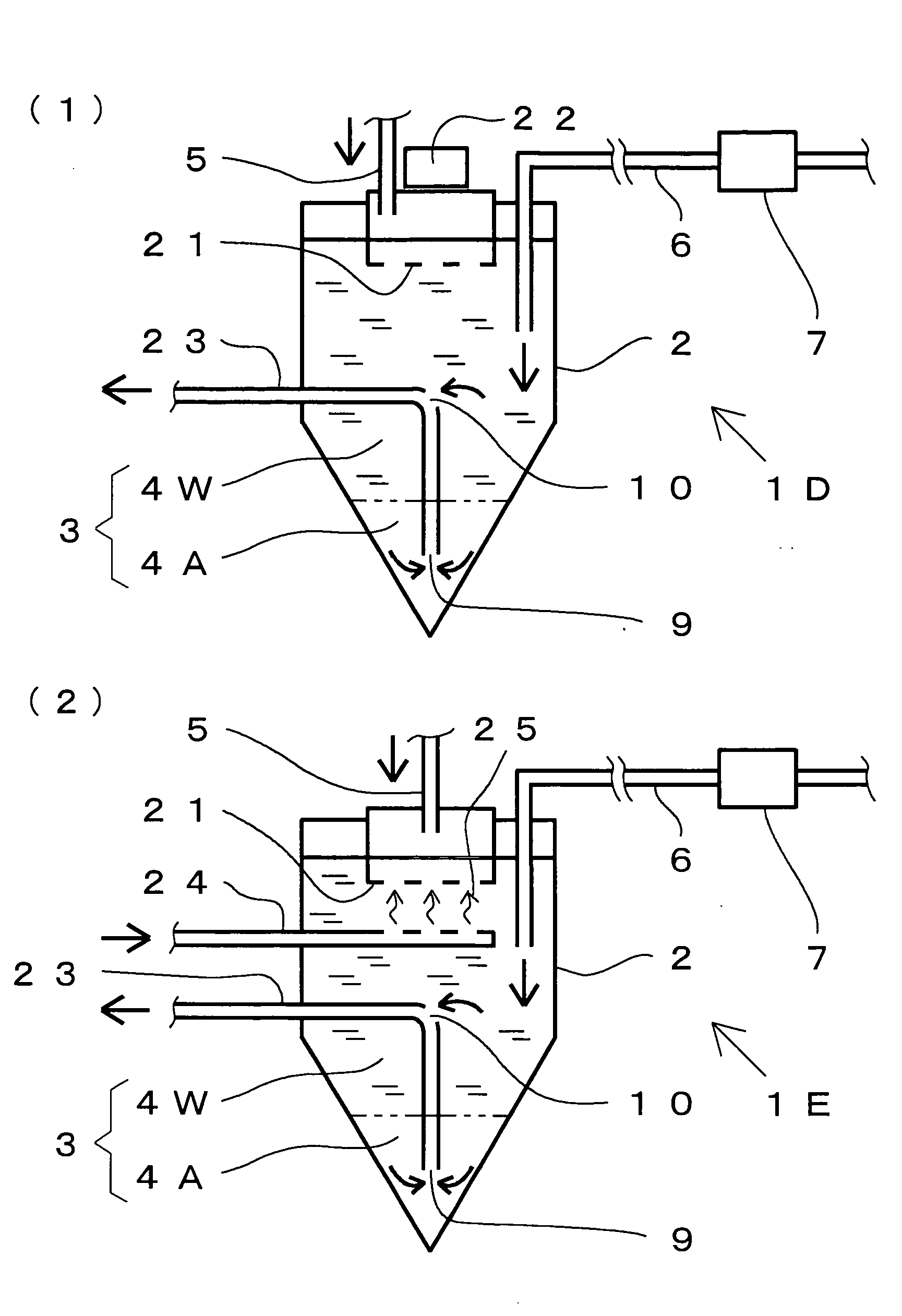
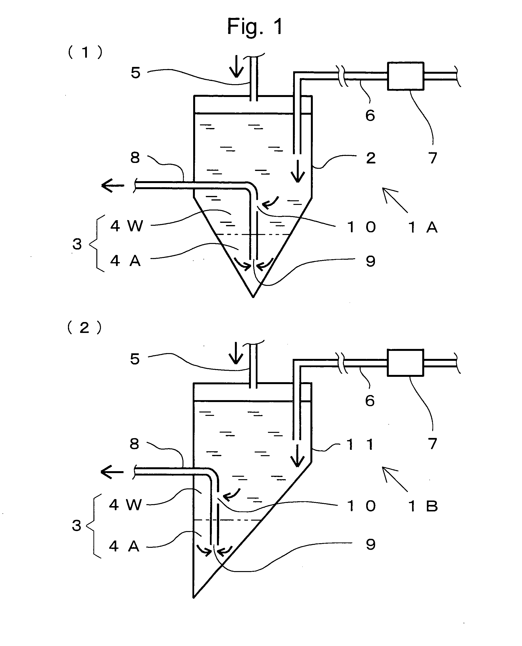
[0045]The first embodiment of the system for supplying processing water according to the present invention is hereinafter described with reference to FIG. 1. FIG. 1(1) is a pipeline diagram schematically showing the configuration of a system for supplying processing water according to the first embodiment, and FIG. 1(2) is a pipeline diagram schematically showing the configuration of a system for supplying processing water according to a variation of the first embodiment. For the purpose of simplicity, some components are appropriately omitted or depicted in an exaggeratedly schematic form in any of the figures used in the following description.

[0046]As shown in FIG. 1(1), the system 1A for supplying processing water according to the present embodiment includes a tapered tank 2 with its lower portion shaped like a cone pointing downwards. In this tapered tank 2, processing water 3 containing an abrasive is stored. The “tapered tank 2” in this description means any tank having a lowe...

second embodiment

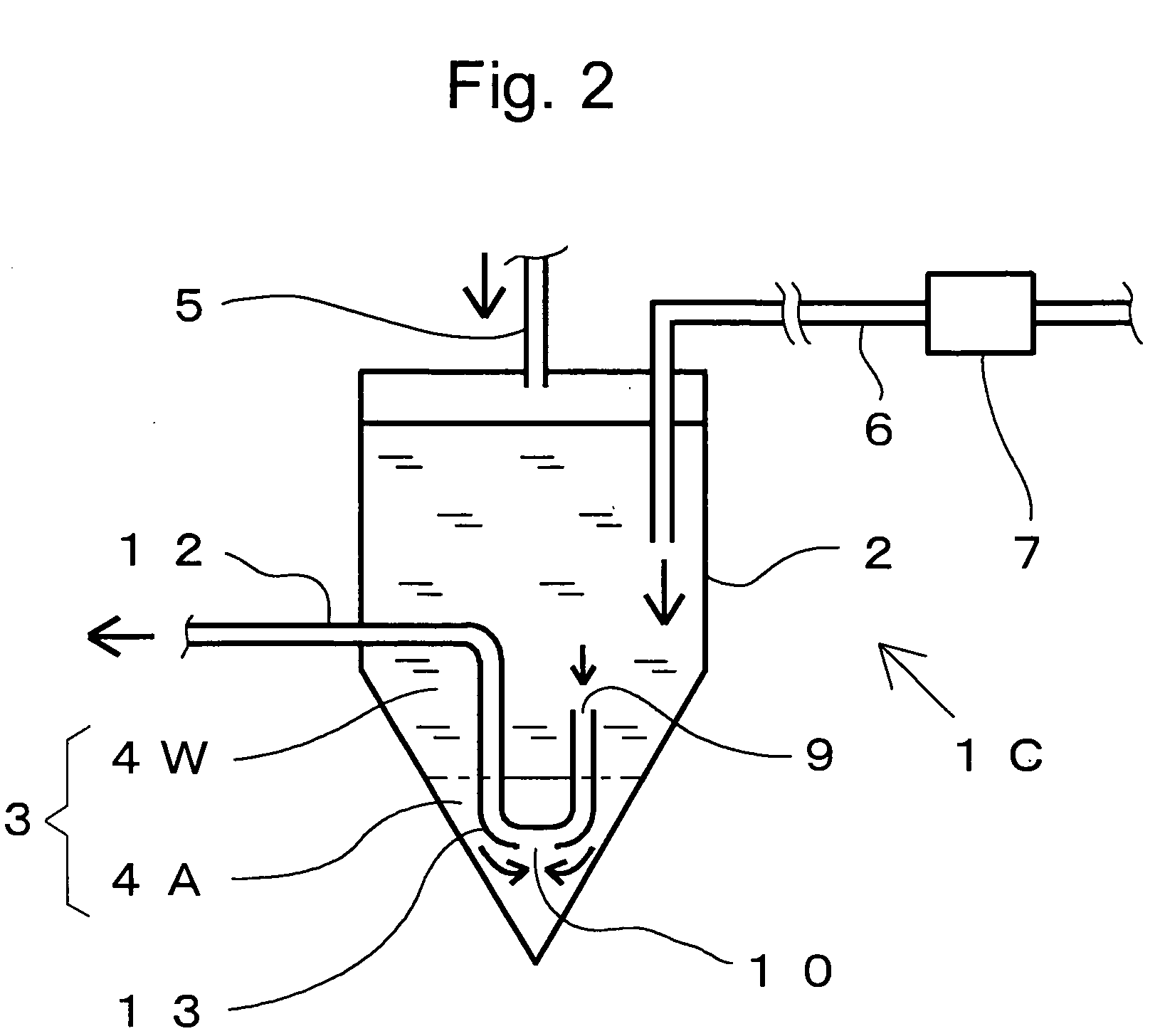
[0060]The second embodiment of the system for supplying processing water according to the present invention is hereinafter described with reference to FIG. 2. FIG. 2 is a pipeline diagram schematically showing the configuration of the system for supplying processing water according to the present embodiment. In any of the drawings used in the following descriptions, the components identical to those shown in FIG. 1 are denoted by the same numerals, and the explanations of those components will be omitted.

[0061]The system 1C for supplying processing water shown in FIG. 2 is characterized by the shape of the delivery pipe 12, which has a U-shaped bend 13 located inside the tapered tank 2. The opening 9 is formed at the inlet end of the bend 13 (i.e. the upper right end of the U shape), and the suction port 10 is formed in the lower portion of the bend 13. The delivery pipe 12 is arranged so that the opening 9 is located within the clear-water portion 9 and the suction port 10 within t...

third embodiment

[0063]The third embodiment of the system for supplying processing water according to the present invention is hereinafter described with reference to FIG. 3. FIGS. 3(1) and 3(2) are sectional views each showing an end of the delivery pipe used in the system for supplying processing water according to the present embodiment. These delivery pipes are characterized in that the area of the opening formed at the end is larger than the cross sectional area of the delivery pipe.

[0064]The end of the delivery pipe 14 shown in FIG. 3(1) is shaped like an inverted funnel. The end of the delivery pipe 15 shown in FIG. 3(2) is shaped like an obliquely cut pipe. The opening 9 at the delivery pipe 15 is created by cutting off a portion corresponding to the side surface of the delivery pipe 15 (i.e. a portion that was originally a part of the side surface of the delivery pipe 15).

[0065]As is evident from FIG. 3(1), the area of the opening 9 at the end of the delivery pipe 14 is larger than the sect...


PUM

PropertyMeasurementUnit
Poweraaaaaaaaaa
Currentaaaaaaaaaa
Currentaaaaaaaaaa

Abstract

The present invention provides a system 1A for supplying processing water 3, which is used in the operation of processing a target object with a highly pressurized jet of processing water 3 containing an abrasive, including: a tank 2 for storing the processing water 3, having a lower portion substantially tapering downwards; a supply pipe 5 for supplying the processing water 3 to the tank 2; a delivery pipe 8 having an opening 9 located inside the tank 2; a pressure mechanism 7 located outside the tank 2, for pressurizing the processing water 3; and a suction port 10 provided in the side surface of the delivery pipe 8. The processing water 3 in the tank 2 is stratified into a deposition portion 4A, which is a portion where the abrasive is deposited, and a clear-water portion 4W, which is a portion other than the deposition portion 4A and formed by clear water substantially free from the abrasive. The opening 9 is located near an end of the delivery pipe 8 and at a position within the deposition portion 4A, while the suction port 10 is located at a position within the clear-water portion 4W.

Description

TECHNICAL FIELD[0001]The present invention relates to a system and method for supplying processing water, which is used in the operation of processing a target object with a highly pressurized jet of processing water containing an abrasive.BACKGROUND ART[0002]A conventional operation (such as a cutting, machining or polishing operation) using processing water containing an abrasive is hereinafter described. This operation is intended for processing a target object by strongly pressurizing water containing an abrasive and jetting the water onto the object. Such a system is called the abrasive suspension jet system (for example, refer to Non-Patent Document 1).[0003]An example of the abrasive suspension jet system is hereinafter described (for details, refer to Patent Document 1). In this system, a slurry-mixed liquid, which consists of water and a slurry containing an abrasive (e.g. abrasive grains made of alumina), is stored in a cylindrical or prismatic storage tank. The storage ta...

Claims


Application Information

Patent Timeline
IPC IPC(8): B24C9/00B01D33/00
CPCB24C9/006Y10T83/0591Y10T83/364Y02P70/10
Inventor KITAGAWA, YASUYUKIYAMAJI, SHUZOHIBI, TAKAAKITOMIZAWA, KANA
Owner TOWA
Features
  • R&D
  • Intellectual Property
  • Life Sciences
  • Materials
  • Tech Scout
  • Unparalleled Data Quality
  • Higher Quality Content
  • 60% Fewer Hallucinations
Learn More