Touch control device and method thereof

Inactive Publication Date: 2009-05-21
TRENDON TOUCH TECHNOLOGY CORPORATION
View PDF10 Cites 34 Cited by
  • Summary
  • Abstract
  • Description
  • Claims
  • Application Information

AI Technical Summary

Benefits of technology

[0007]In accordance with the present invention, the detection of the location of the depression is carried out by performing scanning operation over one end or both end of each elongate conductive strip of a conductive layer of the touch control device and thus the control of the scanning operation and the scanning circuit required for the scanning operation are both simple.

Problems solved by technology

However, each known technique has its own drawbacks.
For example, some touch control panels require complicated circuit structure for detecting

Method used


Image

  • Touch control device and method thereof
  • Touch control device and method thereof
  • Touch control device and method thereof

Examples


Example

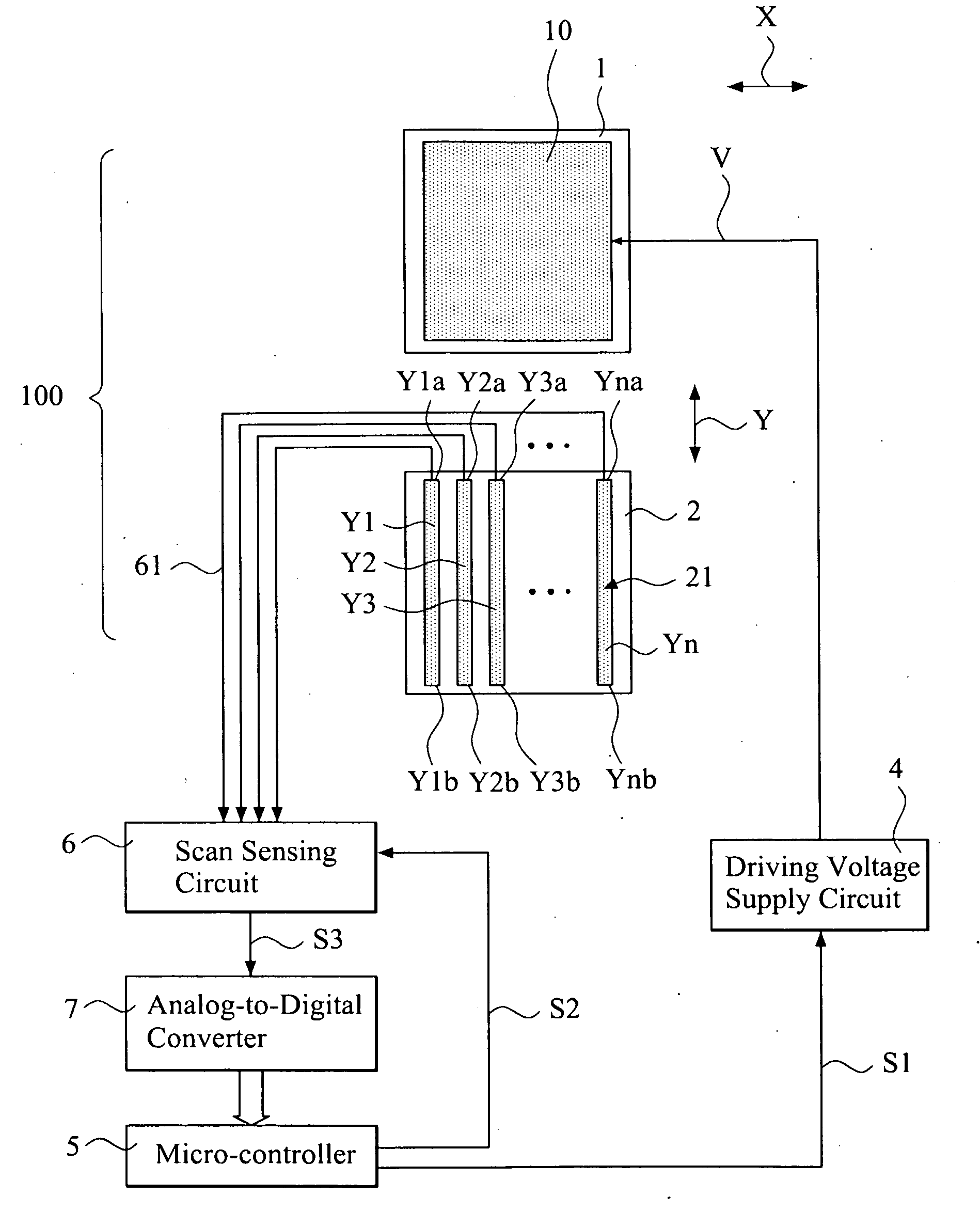
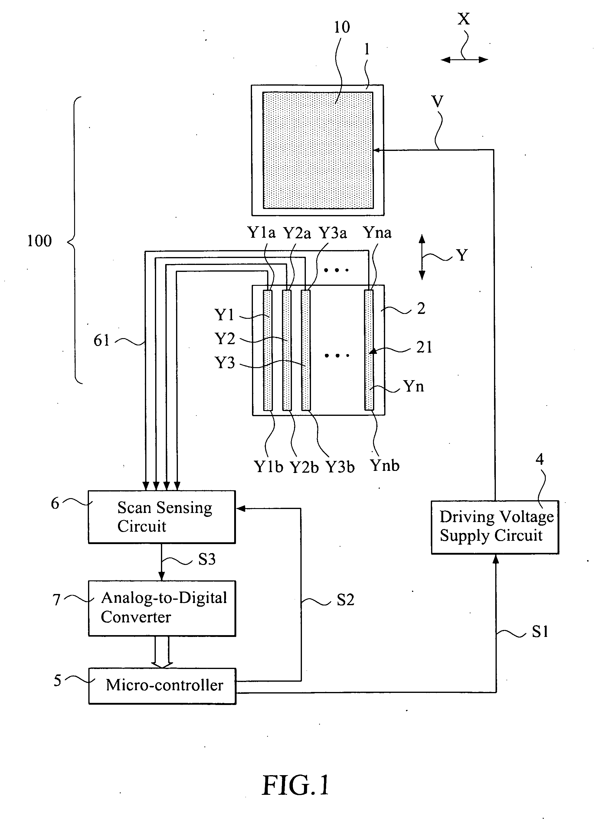
[0023]With reference to the drawings and in particular to FIG. 1, which illustrates a system block diagram of a touch control device in accordance with a first embodiment of the present invention, the touch control device, which is generally designated at 100, comprises a first substrate 1 and a second, opposite substrate 2. The first substrate 1 has a bottom surface on which a first conductive layer 10 is formed in a continuous planar structure. The second substrate 2 has a top surface on which a second conductive layer 21 is formed. For the state-of-art technology of touch control panels, it is often to coat a layer of transparent conductor, such as ITO conductive layer, on a surface of a glass substrate to serve as both the continuous planar structure of the first conductive layer 10 and the second conductive layer 21.

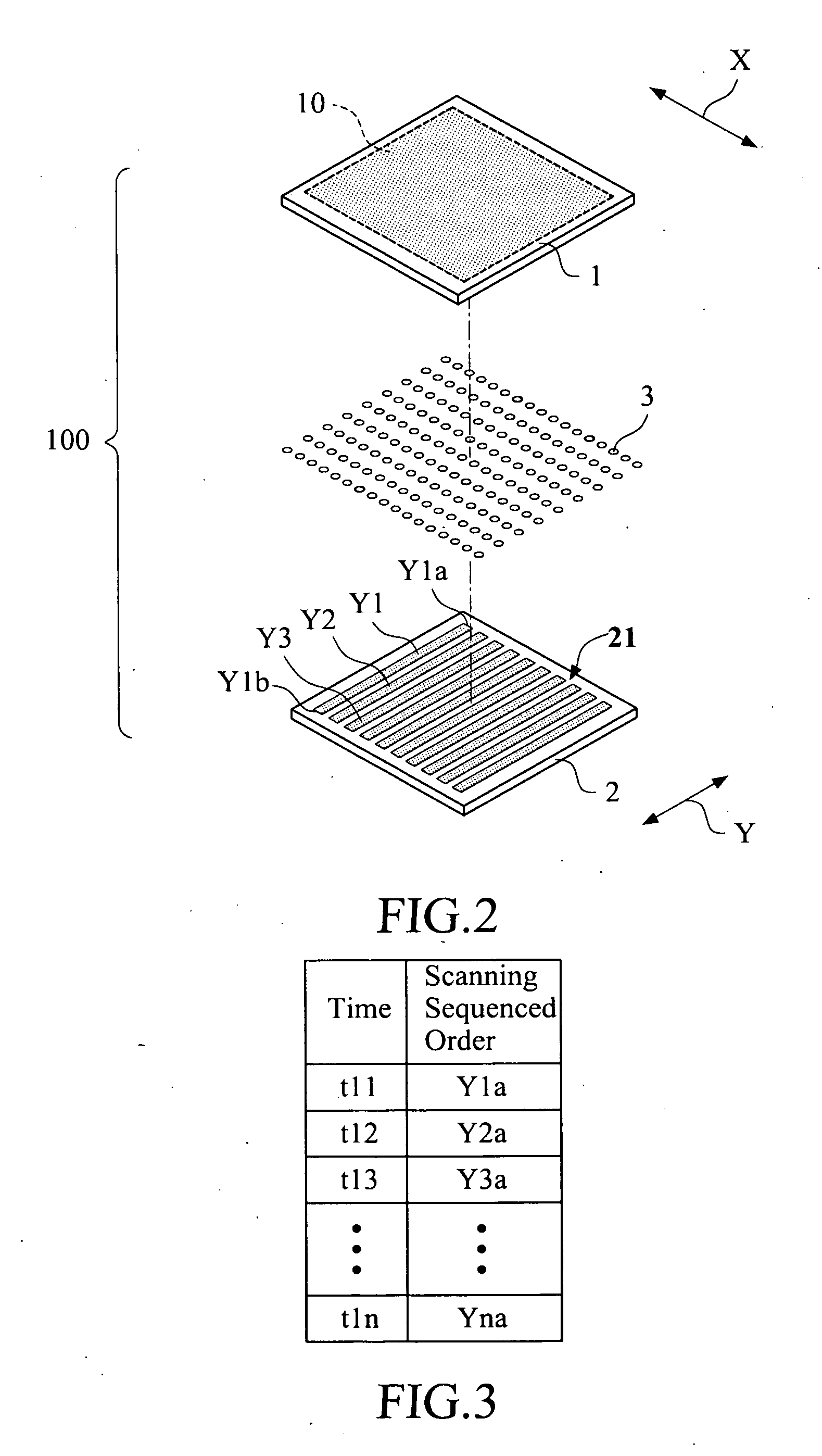
[0024]FIG. 2 shows the continuous planar structure of the first conductive layer 10 opposing the second conductive layer 2 when the first and second substrates 1, 2...


PUM


Abstract

A touch control device and a method thereof are disclosed. A driving voltage is applied to a first conductive layer of the touch control device. A second conductive layer is connected via scanning lines to a scan sensing circuit. To detect the location where a touch or depression occurs, the scan sensing circuit repeatedly and sequentially scans first ends of multiple elongate conductive strips that constitute the second conductive layer. The coordinates of the location of the depression is determined on the basis of the scanning result that the scan sensing circuit performs over the elongate conductive strips of the second conductive layer and the voltage that the first conductive layer applies to one or more of the elongate conductive strips of the second conductive layer that correspond to the location of the depression. The second ends of the elongate conductive strips of the second conductive layer can also be connected to the scan sensing circuit via scanning lines to allow the scan sensing circuit to perform scanning operation over the first and second ends of the elongate conductive strips of the second conductive layer in a sequential and repeated manner.

Description

FIELD OF THE INVENTION[0001]The present invention relates to a touch control device, and in particular to a sequentially-scanning touch control device and a method thereof.BACKGROUND OF THE INVENTION[0002]A conventional touch panel includes a glass substrate having a top surface coated with a layer of transparent conductor, such as ITO conductive layer. The glass substrate and the transparent conductive layer together form a piece of electrically conductive glass panel. The electrically conductive glass panel is provided with another glass substrate or film arranged thereabove, and the another glass substrate or film is coated, on a bottom surface thereof, with a transparent conductive layer, corresponding to the transparent conductive layer of the glass panel. Insulation spacers are arranged between the transparent conductive layers of the glass panel and the film to space the transparent conductive layers.SUMMARY OF THE INVENTION[0003]Various designs and constructions of touch con...

Claims


Application Information

Patent Timeline
IPC IPC(8): H01H1/10
CPCG06F3/045G06F2203/04104G06F3/047G06F3/04166
Inventor LIU, CHEN-YULIN, CHUN-CHI
Owner TRENDON TOUCH TECHNOLOGY CORPORATION
Why Eureka
Try Eureka