
Weld electrode for attractive weld appearance

a welding electrode and attractive technology, applied in the field of welding electrodes, can solve the problems of a lot more difficult to form a design on the sheet surface with commonly used copper electrode materials, and achieve the effect of improving the resistance spot weld appearan

Active Publication Date: 2009-05-21
GM GLOBAL TECH OPERATIONS LLC
View PDF19 Cites 42 Cited by
  • Summary
  • Abstract
  • Description
  • Claims
  • Application Information

AI Technical Summary

Benefits of technology

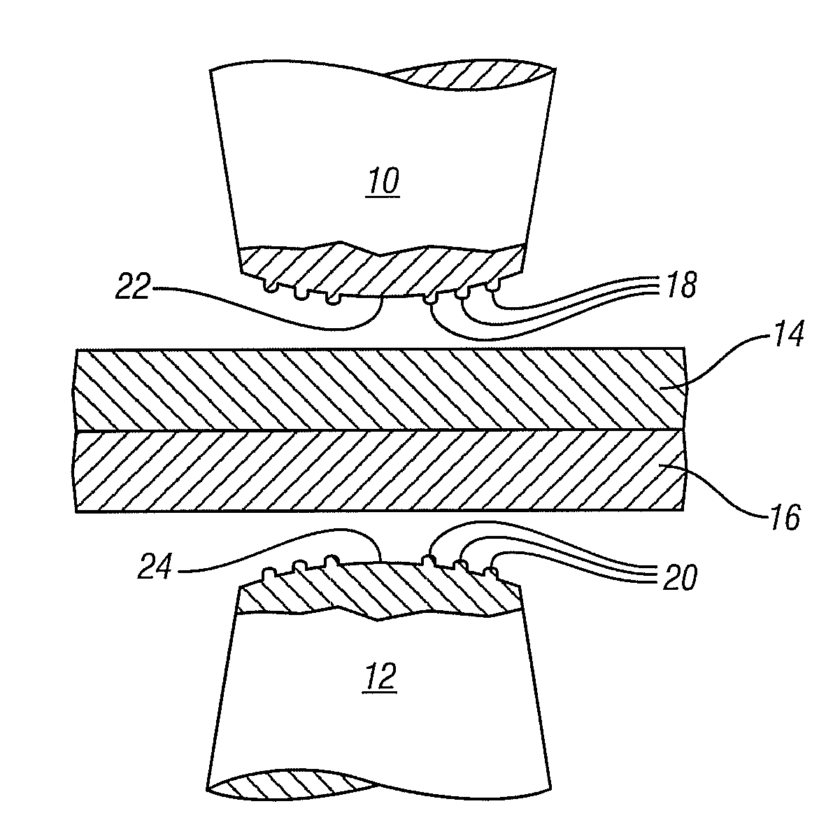
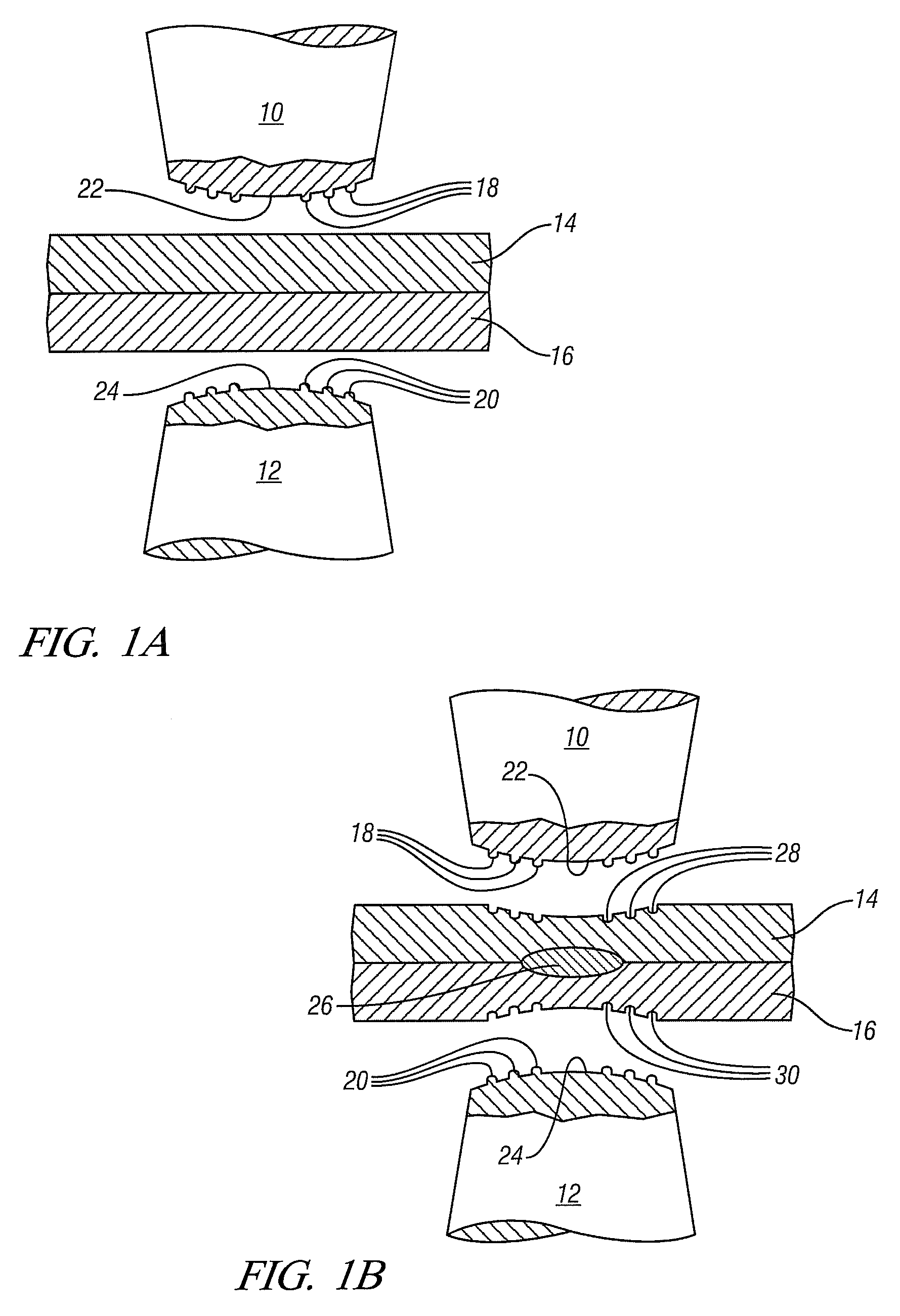
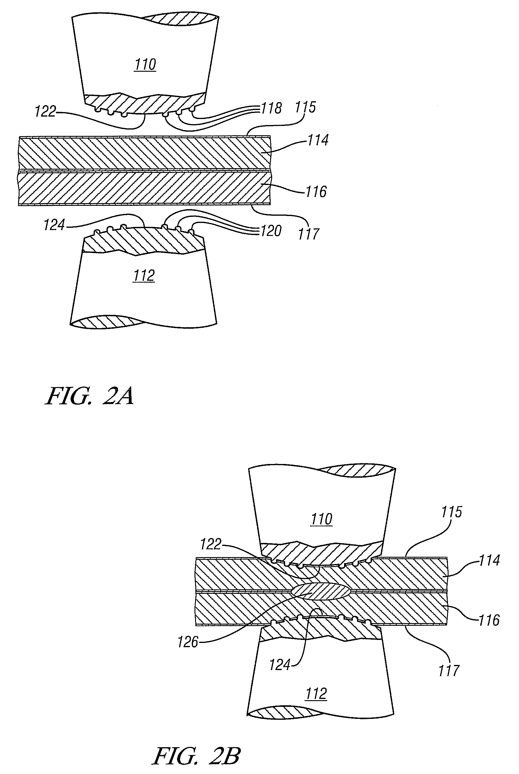
[0011]Formation of the selected design in steel materials may be somewhat different. The higher thermal and electrical resistivity of steel, along with its high melting point, makes it somewhat more difficult to form a design in the sheet surface with commonly used copper electrode materials. However, nearly all steel materials used within automotive vehicle bodies are coated with a layer of zinc or zinc-iron. During the traditional spot welding process, this zinc layer is typically melted early in the welding process and displaced from beneath the electrode by hydraulic pressure. If an electrode is used with a design in the surface, the molten zinc may be trapped within the design so that it is not fully displaced from beneath the welding electrode. Provided that the electrode temperature does not exceed the boiling point of zinc or zinc-iron, once weld current is stopped, the molten zinc or zinc-iron re-solidifies taking the shape of the electrode surface. The design is then incorporated by a combination of sheet deformation and “re-cas ting” of the surface zinc. Since the design is partially formed by recasting zinc, which requires a low temperature to melt, the design can extend well beyond the nugget perimeter where sheet metal is colder and more difficult to form.

Problems solved by technology

The higher thermal and electrical resistivity of steel, along with its high melting point, makes it somewhat more difficult to form a design in the sheet surface with commonly used copper electrode materials.
If an electrode is used with a design in the surface, the molten zinc may be trapped within the design so that it is not fully displaced from beneath the welding electrode.

Method used


Image

  • Weld electrode for attractive weld appearance
  • Weld electrode for attractive weld appearance
  • Weld electrode for attractive weld appearance

Examples


Embodiment Construction

[0026]One or more protrusion and / or intrusion elements are conceived, determined, and formed on the weld face of an electrical resistance spot weld electrode. These elements serve to suitably engage a sheet surface to be welded to form a suitable spot weld nugget between the contacting sheet surfaces. But the elements also are shaped to provide an attractive appearance in a visible welded surface when viewed by an observer.

[0027]Accordingly, the protrusions and / or intrusions must meet a combination of requirements. First, excessive indentation of the sheet material is to be avoided. Excessive indentation or metal thinning may weaken the weld and / or surrounding sheet metal. For a weld consisting of two or more sheets, indentation occurs on the outer surfaces of the two outermost sheets. The amount of indentation is typically more important for the thinner of the two sheets, since any given level of indentation makes up a larger portion of the thickness of the thinner sheet. In all ca...


PUM

PropertyMeasurementUnit
heightaaaaaaaaaa
thicknessaaaaaaaaaa
thicknessaaaaaaaaaa

Abstract

Weld faces of electrodes for resistance spot welding are formed with a suitable area of protrusions and / or intrusions. The size, shape, and elevation or depths of the protrusions or intrusions are determined for the formation of suitable spot welds in and between metal workpieces such as aluminum or steel panels for vehicle bodies. The protrusions or intrusions are also conceived and used to form an image on at least a visible surface of the welded article to produce an attractive appearance on the surface of the welded sheet.

Description

[0001]This application is a continuation-in-part of co-pending application Ser. No. 12 / 251,635, filed Oct. 15, 2008 and titled, “Welding Electrode for Attractive Weld Appearance, which, in turn, is a continuation-in-part of co-pending application Ser. No. 11 / 536,001, filed Sep. 28, 2006 and titled, “Welding Electro de with Contoured Face. The text and drawings of co-pending application Ser. No. 11 / 536,001 are incorporated herein by reference.TECHNICAL FIELD[0002]This invention pertains to electrodes for the formation of electrical resistance spot welds between two or more sheet metal layers. More specifically this invention pertains to welding electrodes for forming of high quality weld nuggets between the metal layers and for simultaneously forming a pleasing pattern or image at the position where the welding electrode contacts the surface.BACKGROUND OF THE INVENTION[0003]The above identified parent application describes welding electrodes with a round weld face for contact with a ...

Claims


Application Information

Patent Timeline
Patent Type & Authority Applications(United States)
IPC IPC(8): B23K11/11
CPCB23B5/166B23K11/115C21D7/13B23K11/3063B23K11/3009
Inventor SIGLER, DAVID R.SCHROTH, JAMES G.
Owner GM GLOBAL TECH OPERATIONS LLC
Learn More