Organic electroluminescent display panel and method for manufacturing the same
- Summary
- Abstract
- Description
- Claims
- Application Information
AI Technical Summary
Benefits of technology
Problems solved by technology
Method used
Image
Examples
embodiment 1
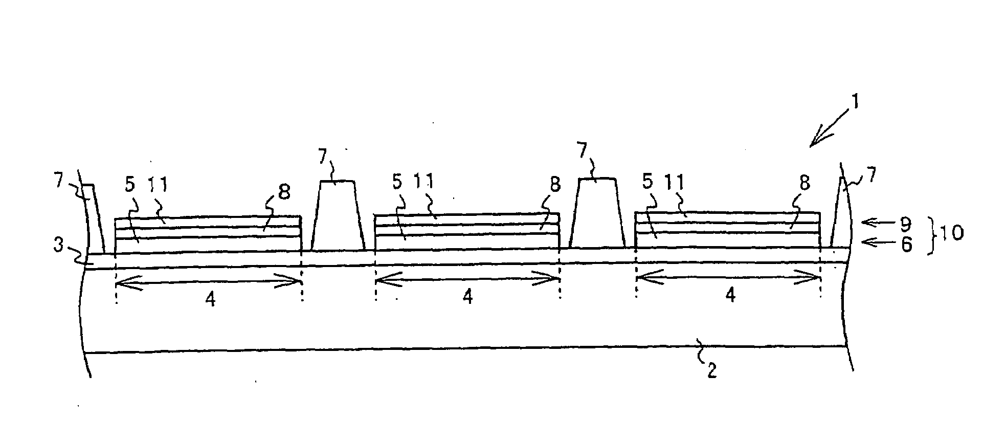
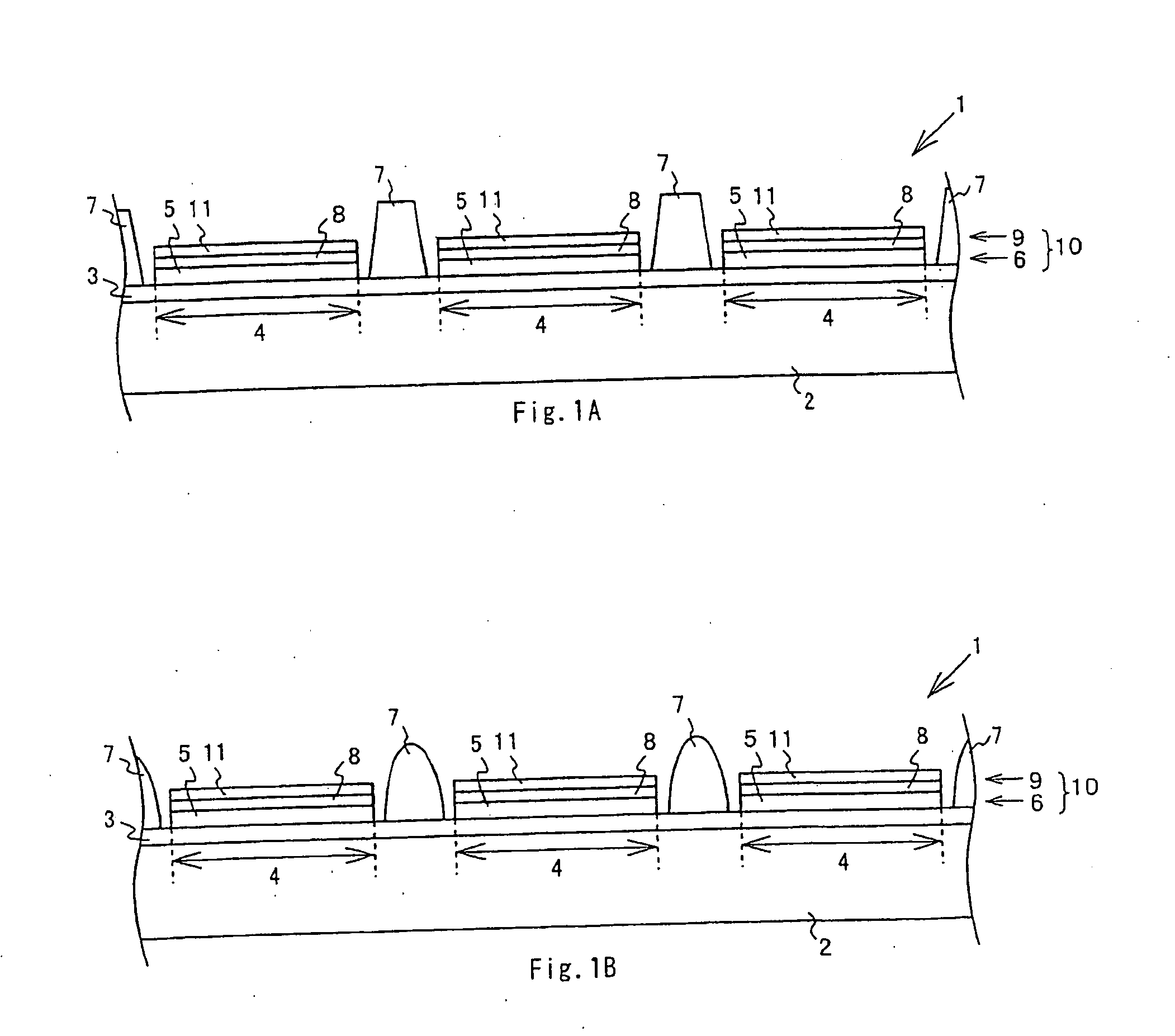
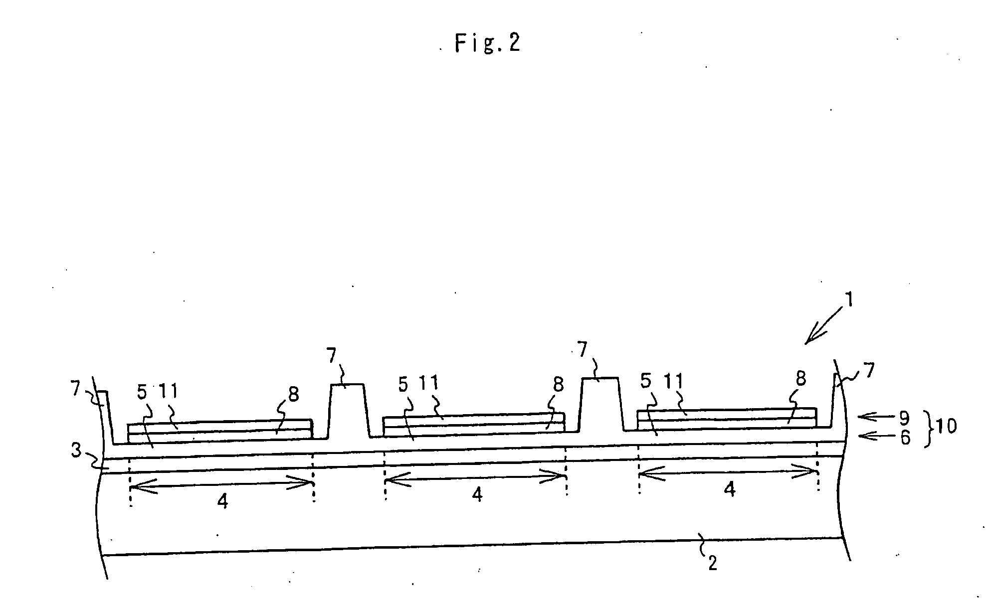
[0023]As shown in FIG. 1A, an organic EL display panel 1 has a substrate 2 made of glass, resin, or the like and a first display electrode 3 made of an electroconductive material such as indium tin oxide (hereinafter referred to as ITO) and provided on the main face of the substrate 2. The first display electrode 3 may be disposed so as to form a striped or other pattern.
[0024]A plurality of pixel light-emitting regions 4 are formed in the first display electrode 3 provided on the substrate2, and a first thin-film piece 5 is disposed in each of the pixel light-emitting regions 4. This group of first thin-film pieces forms a first functional layer 6. The first functional layer is composed of at least one organic material layer, and may, for example, be composed of a hole injection layer. When the first functional layer is made of a material with a low molecular weight, it may be formed by vapor deposition or another such dry process. When the first functional layer is made of a mater...
embodiment 2
[0032]FIG. 3 illustrates a modification to the above-described organic EL display panel. As shown in FIG. 3, the organic EL display panel 1 may be configured such that insulating films 12 are provided on the first display electrode 3. A plurality of windows 13 are formed in the insulating films 12, and these windows 13 expose the first display electrode 3 and demarcate the pixel light-emitting regions 4. The insulating films 12 are made of an organic material such as polyimide, or an inorganic material such as silicon oxide. The insulating films may be made of a material with poor wettability.
[0033]First thin-film pieces 5 made of an organic material having a hole injection function, for example, are disposed in the pixel light-emitting regions 4 demarcated by the insulating films 12, thereby forming a first functional layer 6. Mask spacers 7 are provided on the insulating films 12, and these mask spacers 7 are made of the same material as the first functional layer 6 provided in th...
embodiment 3
[0036]An embodiment will be described in which barriers separating adjacent second display electrodes are provided in the organic EL display panel. As shown in FIG. 4; the organic EL display panel 1 is configured such that a first display electrode 3 having electrode pieces disposed in a striped pattern, for example, is provided on the main face of the substrate 2. Insulating films 12 that demarcate the pixel light-emitting regions 4 are provided on the first display electrode 3. A plurality of barriers 14 extending (or protruding) from the main face of the substrate 2 are provided on the insulating films 12. The barriers 14 have at their upper part an overhang that protrudes parallel to the substrate, and may have a cross sectional shape that is inverted trapezoidal, for example. The barriers 14 may be made of a resin material. The barriers may be made of a material with poor wettability. The insulating films 12 may be omitted, and the barriers 14 may be formed directly on the firs...
PUM
 Abstract
Description
Claims
Application Information
 - R&D
- Intellectual Property
- Life Sciences
- Materials
- Tech Scout
- Unparalleled Data Quality
- Higher Quality Content
- 60% Fewer Hallucinations
Browse by: Latest US Patents, China's latest patents, Technical Efficacy Thesaurus, Application Domain, Technology Topic, Popular Technical Reports.
© 2025 PatSnap. All rights reserved.Legal|Privacy policy|Modern Slavery Act Transparency Statement|Sitemap|About US| Contact US: help@patsnap.com


