Display Plate for Solar Cell Apparatus and Method of Producing Display Plate for Solar Cell Apparatus
a technology of solar cell and display plate, which is applied in the direction of electric winding, instruments, and solar cell, can solve the problems of spoiling the beauty of portable watches, restricting the material of display plates, and spoiling the appearance quality of portable watches, so as to increase the design variation, the effect of solar cell electric power generation and enlarging the design variation
- Summary
- Abstract
- Description
- Claims
- Application Information
AI Technical Summary
Benefits of technology
Problems solved by technology
Method used
Image
Examples
embodiment 1
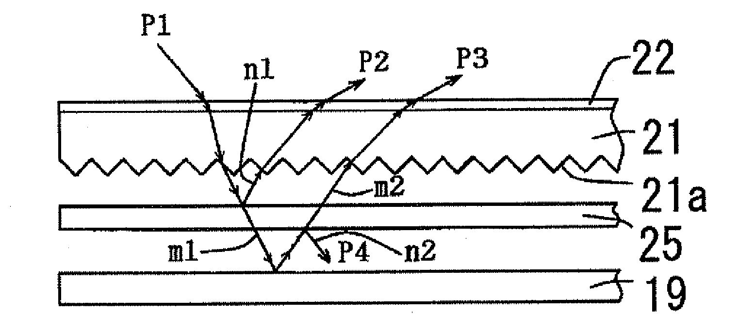
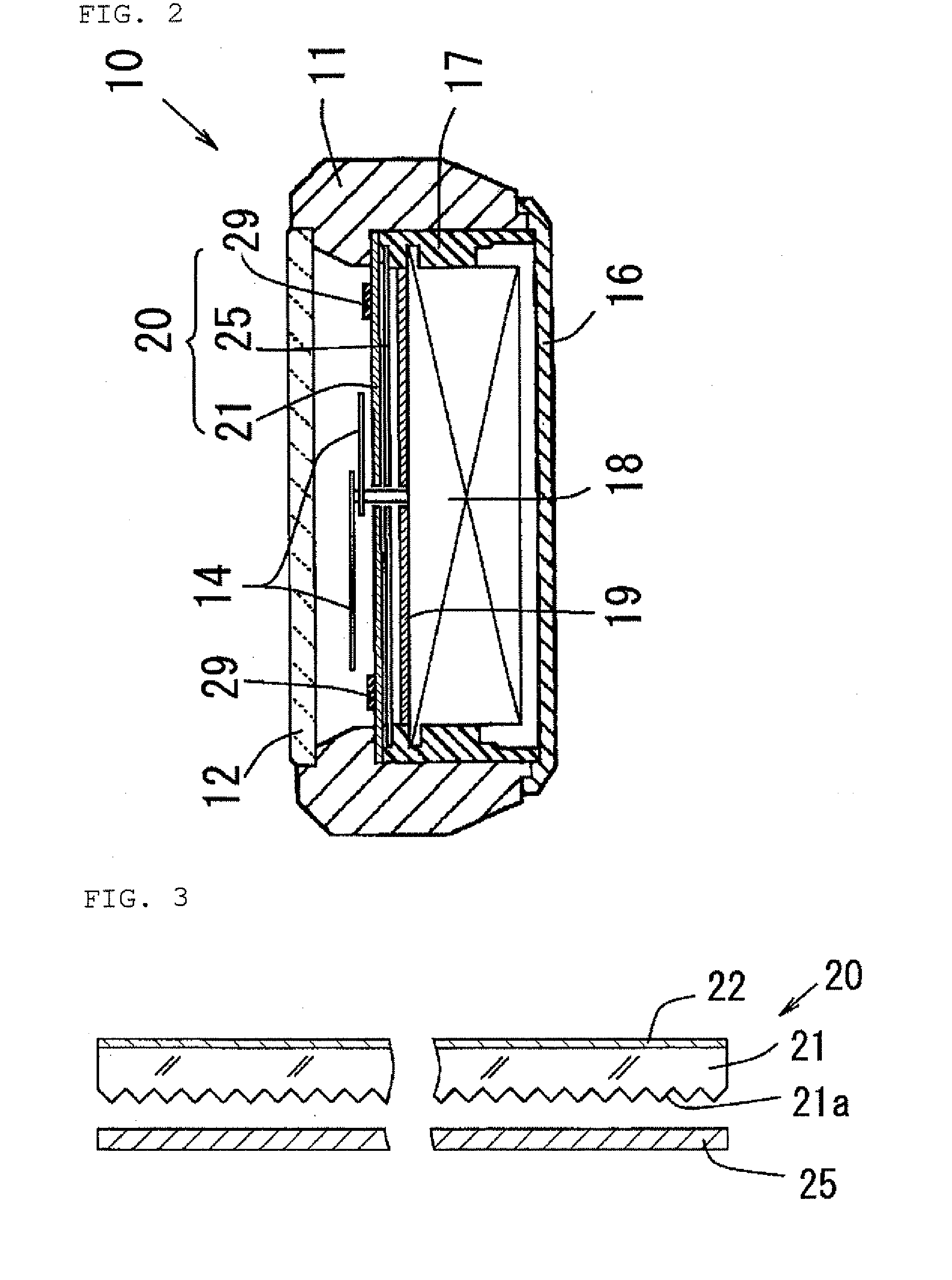
[0503]FIG. 3 is a pivotal partially cross-sectional view of a first embodiment of the display plate for a solar cell device in accordance with the present invention. FIG. 4 is a view for illustrating a reflection polarizing plate shown in FIG. 3. FIG. 5 is a view for illustrating an operation of the reflection polarizing plate shown in FIG. 3.
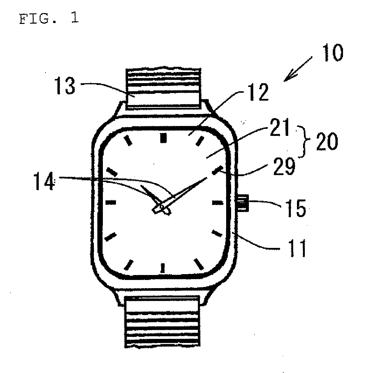
[0504]As shown in FIG. 3, a numeral 20 represents a display plate 20 for a solar watch to be attached to the solar watch 10 as described above (hereafter referred to as a display plate for a watch).
[0505]The display plate 20 for a watch is composed of the light transmission substrate 21, a first transmission colored film 22 formed on the light transmission substrate 21, and the reflection polarizing plate 25 that is a light transmission reflecting plate formed under the light transmission substrate 21.
[0506]An index is mounted on the first transmission colored film 22 although this is not shown in FIG. 3. The description of the index is omitted...
embodiment 2
[0540]FIG. 6 is a pivotal partially cross-sectional view of a second embodiment of the display plate for a solar cell device in accordance with the present invention.
[0541]As shown in FIG. 6, for a display plate 30 for a watch in accordance with this embodiment, a first transmission colored film 32 is formed on a light transmission substrate 31, and a transparent film 33 is formed on the first transmission colored film 32. A reflection polarizing plate 35 that functions as a light transmission reflecting plate is formed under the light transmission substrate 31.
[0542]Consequently, the display plate 30 for a watch in accordance with this embodiment is composed of the light transmission substrate 31, the first transmission colored film 32 formed on the light transmission substrate 31, the transparent film 33, and the reflection polarizing plate 35 formed under the light transmission substrate 31.
[0543]The reflection polarizing plate 35 in accordance with this embodiment is a reflectio...
embodiment 3
[0555]FIG. 7 is a pivotal partially cross-sectional view of a third embodiment of the display plate for a solar cell device in accordance with the present invention.
[0556]As shown in FIG. 7, for a display plate 40 for a watch in accordance with this embodiment, a prism reflecting surface 41a is formed on the bottom surface of a light transmission substrate 41, and a first transmission colored film 42 is formed on the light transmission substrate 41. Moreover, a second transmission colored film 46 is formed on a reflection polarizing plate 45 that is a light transmission reflecting plate.
[0557]Consequently, the display plate 40 for a watch in accordance with this embodiment is composed of the light transmission substrate 41, the first transmission colored film 42 formed on the light transmission substrate 41, the reflection polarizing plate 45, and the second transmission colored film 46 formed on the reflection polarizing plate 45.
[0558]The light transmission substrate 41 in accorda...
PUM
| Property | Measurement | Unit |
|---|---|---|
| thickness | aaaaa | aaaaa |
| transmittance | aaaaa | aaaaa |
| transmittance | aaaaa | aaaaa |
Abstract
Description
Claims
Application Information
 - R&D
- Intellectual Property
- Life Sciences
- Materials
- Tech Scout
- Unparalleled Data Quality
- Higher Quality Content
- 60% Fewer Hallucinations
Browse by: Latest US Patents, China's latest patents, Technical Efficacy Thesaurus, Application Domain, Technology Topic, Popular Technical Reports.
© 2025 PatSnap. All rights reserved.Legal|Privacy policy|Modern Slavery Act Transparency Statement|Sitemap|About US| Contact US: help@patsnap.com


