Motor control system and hybrid electric vehicle

Pending Publication Date: 2022-09-22
TOYOTA JIDOSHA KK
View PDF0 Cites 0 Cited by
  • Summary
  • Abstract
  • Description
  • Claims
  • Application Information

AI Technical Summary

Problems solved by technology

When a motor controller is configured to control the motor generator in accordance with an instruction provided through communication, the motor controller is not able to receive the instruction in the event of a communication fault.
When the relay is provided

Method used


Image

  • Motor control system and hybrid electric vehicle
  • Motor control system and hybrid electric vehicle
  • Motor control system and hybrid electric vehicle

Examples


Embodiment Construction

[0023]Hereinafter, an embodiment will be described with reference to the accompanying drawings. Like reference signs denote the same or corresponding portions in the drawings, and the description thereof will not be repeated.

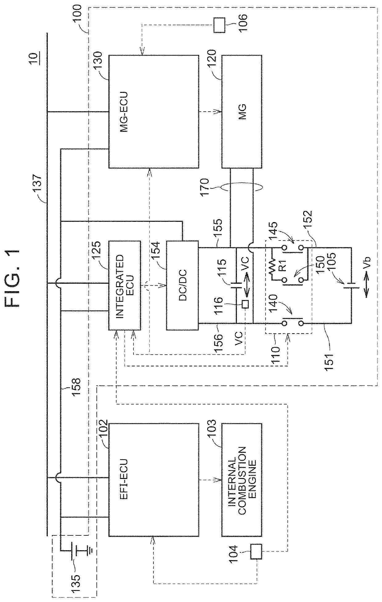
[0024]FIG. 1 is a block diagram showing the overall configuration of a vehicle to which a motor control system according to the present embodiment is applied. The vehicle 10 is a so-called mild hybrid electric vehicle. The vehicle 10 runs when a motor generator (MG) is supplementarily driven for an internal combustion engine.

[0025]As shown in FIG. 1, the vehicle 10 includes a motor control system 100, an electrical fuel injection (EFI)-electronic control unit (ECU) 102, the internal combustion engine 103, rotation speed sensors 104, 106, and a bus 137.

[0026]The motor control system 100 includes a battery 105, a system main relay (SMR) 110, a capacitor 115, a voltage sensor 116, the motor generator (MG) 120, a battery 135, a DC-DC converter 154, an MG-ECU 130, an...


PUM


Abstract

A motor control system includes an MG, a battery, an SMR, and an MG-ECU. The MG-ECU is configured to control the MG in accordance with an instruction provided through communication. The MG-ECU is configured to execute autonomous power generation control of the MG in an event of a fault in the communication. The autonomous power generation control is control in which the MG-ECU causes the MG to generate a predetermined voltage not in accordance with the instruction. The MG-ECU is configured to, when a fault is detected in the communication, start the autonomous power generation control after the SMR has finished switching from an off state to an on state.

Description

CROSS-REFERENCE TO RELATED APPLICATION[0001]This application claims priority to Japanese Patent Application No. 2021-045468 filed on Mar. 19, 2021, incorporated herein by reference in its entirety.BACKGROUND1. Technical Field[0002]The disclosure relates to a motor control system and, more particularly, to a motor control system including a motor generator.2. Description of Related Art[0003]Japanese Unexamined Patent Application Publication No. 2014-079081 (JP 2014-079081 A) describes a vehicle including a relay provided in an electric circuit between a motor generator and an electrical storage device. When the relay switches from an off state to an on state, current flows through the electric circuit via the relay.SUMMARY[0004]When a motor controller is configured to control the motor generator in accordance with an instruction provided through communication, the motor controller is not able to receive the instruction in the event of a communication fault. Therefore, in the event of...

Claims


Application Information

Patent Timeline
IPC IPC(8): B60W20/10B60W20/40B60W20/20B60L15/00
CPCB60W20/10B60W20/40B60W20/20B60L15/007B60W20/50B60W20/15B60L15/22B60L3/0092B60L3/0084B60L50/61
Inventor MURAKAMI, KOJIYAMAGUCHI, TATSUYANAKANISHI, KENSUKE
Owner TOYOTA JIDOSHA KK
Why Eureka
Try Eureka