Refueling apparatus for sodium-cooled fast reactor and method for the same

a sodium-cooled, fast reactor technology, applied in nuclear engineering problems, nuclear elements, greenhouse gas reduction, etc., can solve the problems of reducing and affecting the detection accuracy of sodium-cooled fast reactors. , the beam width of the leaky ultrasonic wave is reduced, and the radiation angle of the radiation beam may be reduced.

Active Publication Date: 2009-05-21
KOREA HYDRO & NUCLEAR POWER CO LTD +1
View PDF8 Cites 5 Cited by
  • Summary
  • Abstract
  • Description
  • Claims
  • Application Information

AI Technical Summary

Benefits of technology

[0011]Another aspect of the present invention also provides a refueling apparatus and method which may detect a location movement and deflection of a fuel assembly while refueling, and thereby may improve safe handling of the fuel assembly.
[0012]Another aspect of the present invention also provides a refueling apparatus and method which is integrally formed with an ultrasonic examination apparatus, and thereby may simplify a refueling process and an in-vessel component in a reactor vessel.
[0018]The refueling apparatus includes the waveguide sensor unit, and thereby may refuel the reactor core in the reactor vessel while detecting the condition of reactor core in the reactor vessel through a direction of the refueling unit. Also, the refueling apparatus includes the refueling unit and the waveguide sensor unit which is integrally formed with the refueling unit, and thereby may simplify in-vessel components in the reactor vessel. Also, the refueling apparatus may detect the condition of the inside of the reactor vessel such as the location of the fuel assembly and whether an obstacle exists on a transfer path of nuclear fuel assembly using the ultrasonic signal. Accordingly, a safe handling of the fuel assembly may be improved.
[0023]Accordingly, a scan area detected by the waveguide sensor unit may increase without a mechanical operation.
[0024]When the frequency (f) of the ultrasonic wave incident to the ultrasonic wedge changes, the phase velocity (CP) may change, and thus a radiation angle of a radiation beam, emitted from the waveguide, may change. Accordingly, the scan area detected by the waveguide sensor may increase without a mechanical operation. Also, when a thickness of the other end of the waveguide increases in a lengthwise direction, the phase velocity (CP) increases and the radiation angle of the radiation beam may decrease. Accordingly, an emitted leaky ultrasonic beam may converge. Because the beam width of the leaky ultrasonic wave is reduced, a C-Scan image resolution may be improved.

Problems solved by technology

However, a fuel assembly in a core may be deflected or may be extended by several mm due to high temperature and radiation.
In a conventional art, since fuel assemblies are exchanged without information about the above-described location movement or deflection, safe handling of a fuel assembly may be compromised.
Accordingly, an examination process is complex and a significant amount of time for examination is spent.

Method used


Image

  • Refueling apparatus for sodium-cooled fast reactor and method for the same
  • Refueling apparatus for sodium-cooled fast reactor and method for the same
  • Refueling apparatus for sodium-cooled fast reactor and method for the same

Examples


Embodiment Construction

[0044]Reference will now be made in detail to exemplary embodiments of the present invention, examples of which are illustrated in the accompanying drawings, wherein like reference numerals refer to the like elements throughout. Exemplary embodiments are described below to explain the present invention by referring to the figures.

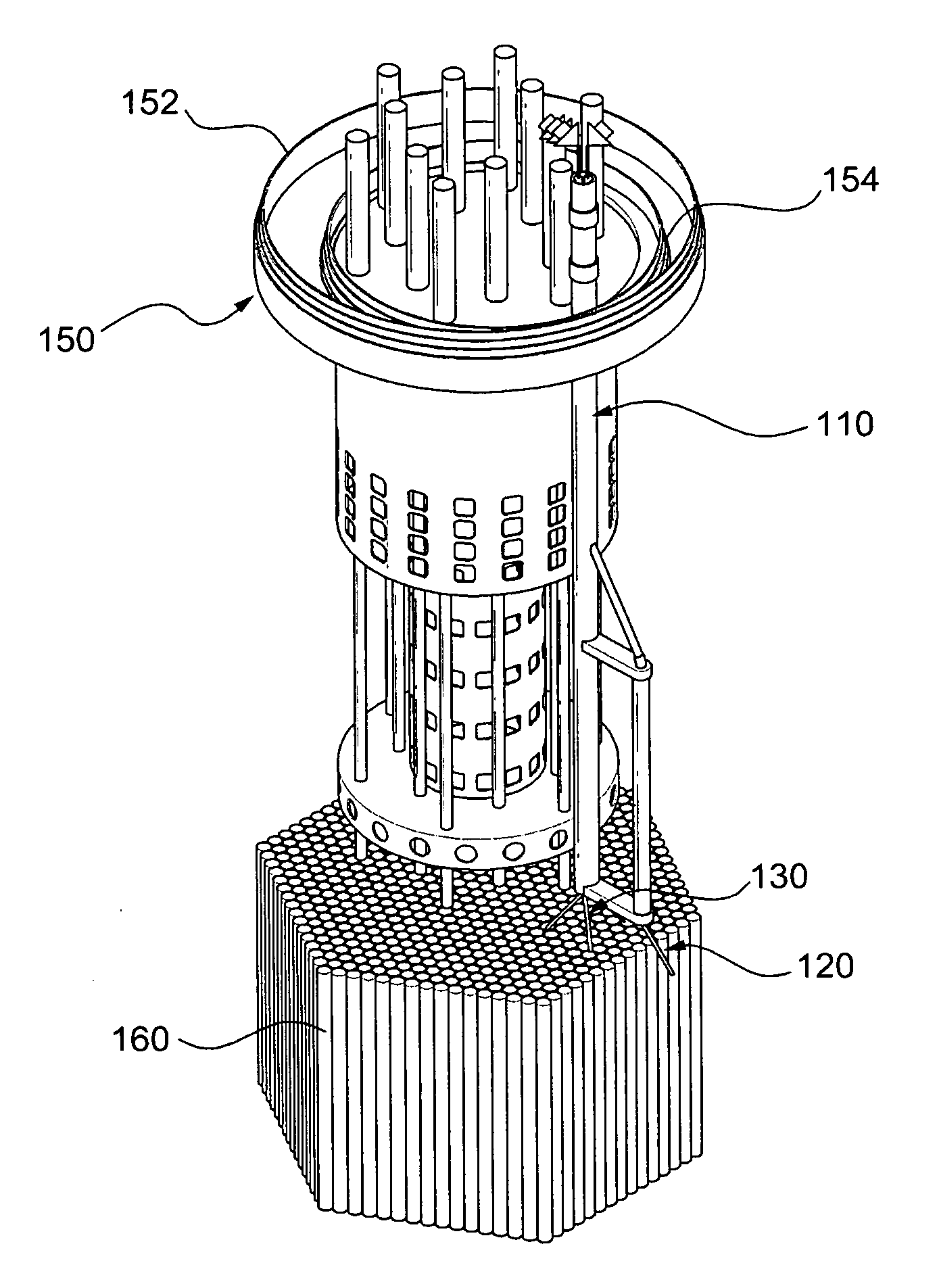
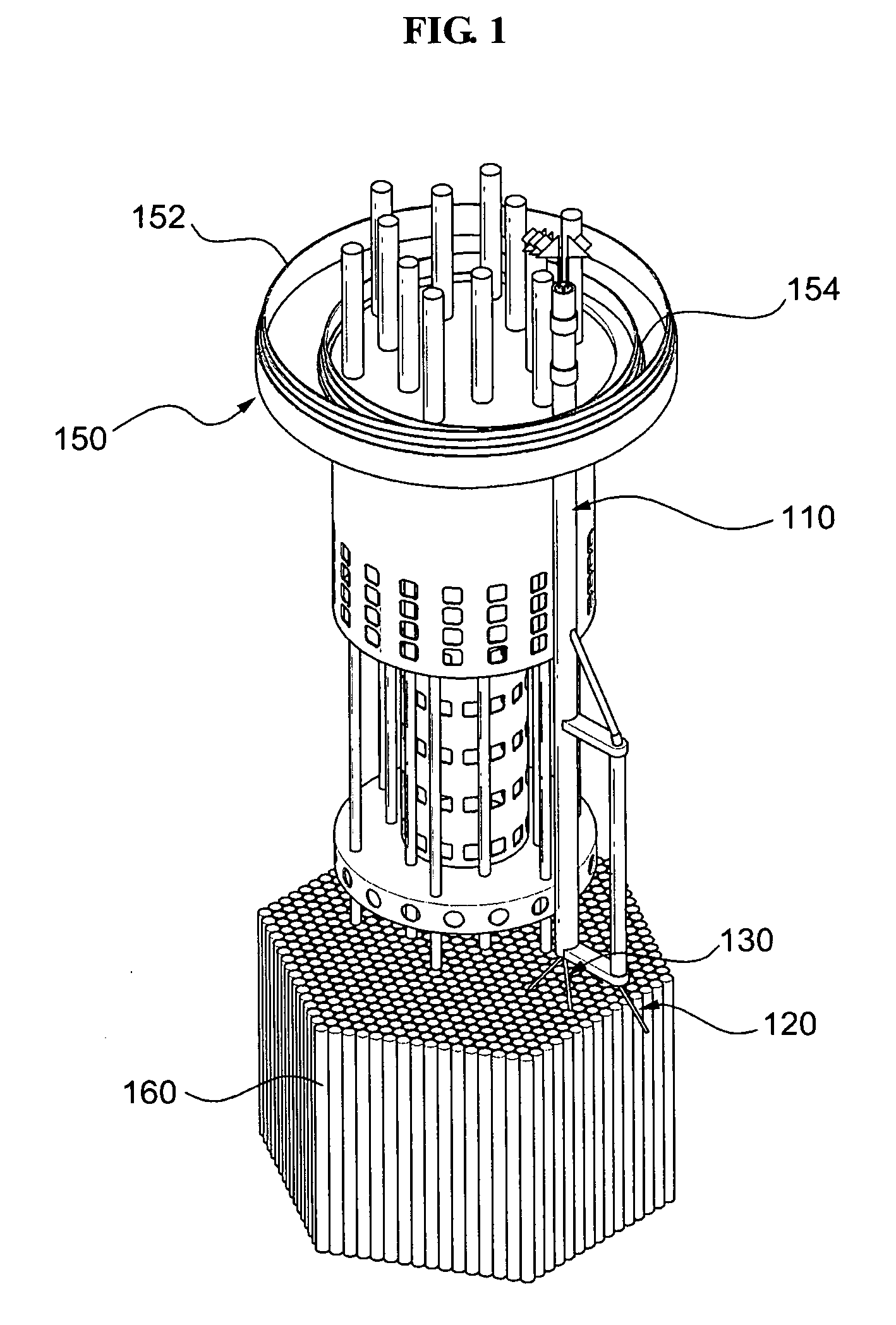
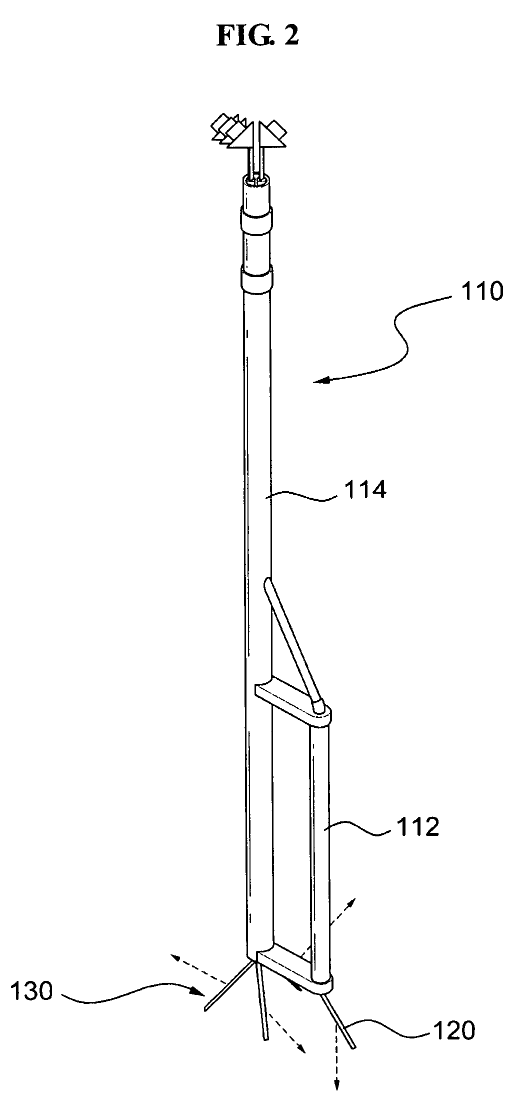
[0045]FIG. 1 is a perspective view illustrating an internal configuration of a reactor vessel equipped with a refueling apparatus according to an exemplary embodiment of the present invention. FIG. 2 is a perspective view illustrating a refueling unit, first and second waveguide sensor units of FIG. 1. FIG. 3 is a perspective view illustrating a first waveguide sensor unit. FIG. 4 is a perspective view illustrating a second waveguide sensor unit.

[0046]As illustrated in FIG. 1, the refueling apparatus according to an embodiment of the present invention may include a refueling unit 110, first waveguide sensor unit 120, and second waveguide sensor unit 130.

[00...


PUM


Abstract

A refueling apparatus for charging nuclear fuel in a reactor vessel, the refueling apparatus including: a refueling unit loading new nuclear fuel to a core or extracting spent nuclear fuel from the core; and a waveguide sensor unit including an ultrasonic wedge to form a Lamb wave, a waveguide with an end connected to the ultrasonic wedge and with another end transmitting the Lamb wave into the reactor vessel, and an ultrasonic sensor connected to the ultrasonic wedge and sensing a reflection signal reflected from an inside of the reactor vessel, the waveguide being formed in a plate shape and mounted in an end of the refueling unit. The waveguide integrally moves with the refueling unit, and the waveguide sensor unit detects a condition of the inside of the reactor vessel, while the refueling unit refuels the fuel assembly in the reactor vessel.

Description

CROSS-REFERENCE TO RELATED APPLICATION[0001]This application claims the benefit of Korean Patent Application No. 10-2007-0118137, filed on Nov. 19, 2007, in the Korean Intellectual Property Office, the disclosure of which is incorporated herein by reference.BACKGROUND OF THE INVENTION[0002]1. Field of the Invention[0003]The present invention relates to a refueling apparatus and method, and more particularly, to a refueling apparatus and method that may simultaneously detect a condition of reactor core in reactor vessel and a fuel assembly in the reactor vessel.[0004]2. Description of Related Art[0005]In a liquid metal fast reactor such as a sodium-cooled fast reactor, refueling is performed by remote control in a closed fuel cycle. Since sodium is opaque and reactive with air, refueling may be performed while a cover of a reactor vessel is not open.[0006]In a conventional art, an ultrasonograph is mounted in a reactor, and a refueling apparatus is transferred to a predetermined loca...

Claims


Application Information

Patent Timeline
Patent Type & Authority Applications(United States)
IPC IPC(8): G21C17/00G21C19/00
CPCG21C19/205G21Y2002/201G21Y2002/207G21Y2004/504G21Y2002/402G21Y2004/30G21Y2004/40G21Y2002/304Y02E30/30G21C19/19
Inventor JOO, YOUNG- SANGPARK, CHANG- GYUKIM, SEOK- HOONKOO, GYEONG- HOILEE, JAE- HAN
Owner KOREA HYDRO & NUCLEAR POWER CO LTD
Why Eureka
Try Eureka