Unlock instant, AI-driven research and patent intelligence for your innovation.
Image forming apparatus
Active Publication Date: 2009-05-21
CANON KK
View PDF6 Cites 13 Cited by
Summary
Abstract
Description
Claims
Application Information
AI Technical Summary
This helps you quickly interpret patents by identifying the three key elements:
Problems solved by technology
Method used
Benefits of technology
Benefits of technology
[0017]The present invention has been made in view of the above-mentioned points, and it is therefore an object of the present invention to provide an image forming apparatus that can stabilize loop control of a recording material and can prevent occurrence of a trouble in the image forming process regardless of endurance states of fixing means and conveying means, using environment of the image forming apparatus and a type of the recording material.
[0020]According to the present invention, the loop control can be stabilized even in the image forming apparatus using the fixing unit having a long designed life.
Problems solved by technology
Therefore, if a recording material conveying speed of the fixing portion is faster than a recording material conveying speed of the transferring portion, the recording material becomes stretched resulting in deterioration of image quality such as a color drift or a transferring shake in a transferring step.
In contrast, if the recording material conveying speed of the transferring portion is faster than the recording material conveying speed of the fixing portion, a loop (or curve) becomes too large resulting in lack of space for maintaining an appropriate loop shape.
Therefore, there may be a problem that a surface of an unfixed image is rubbed in the apparatus.
However, if the fixing unit has a long period of life, it is considered that a difference between the recording material conveying speed when the fixing unit is new and the recording material conveying speed when the fixing unit is close to the end of its life is large.
As a result, the loop amount of the recording material is hardly controlled within a desired range, and hence gross unevenness corresponding to the switching of the fixing speed or unevenness of overhead transparency (OHT) may occur.
In a worse case, paper wrinkle due to unstable conveying, stretching between the transferring means and the fixing portion, image abrasion due to an increase of the loop, and color drift of each color due to a variation of a load on the recording material may also occur.
Method used
Image
Click on the blue label to locate the original text in one second.
Reading with bidirectional positioning of images and text.
Examples
example 1
Image Forming Apparatus (FIG. 1)
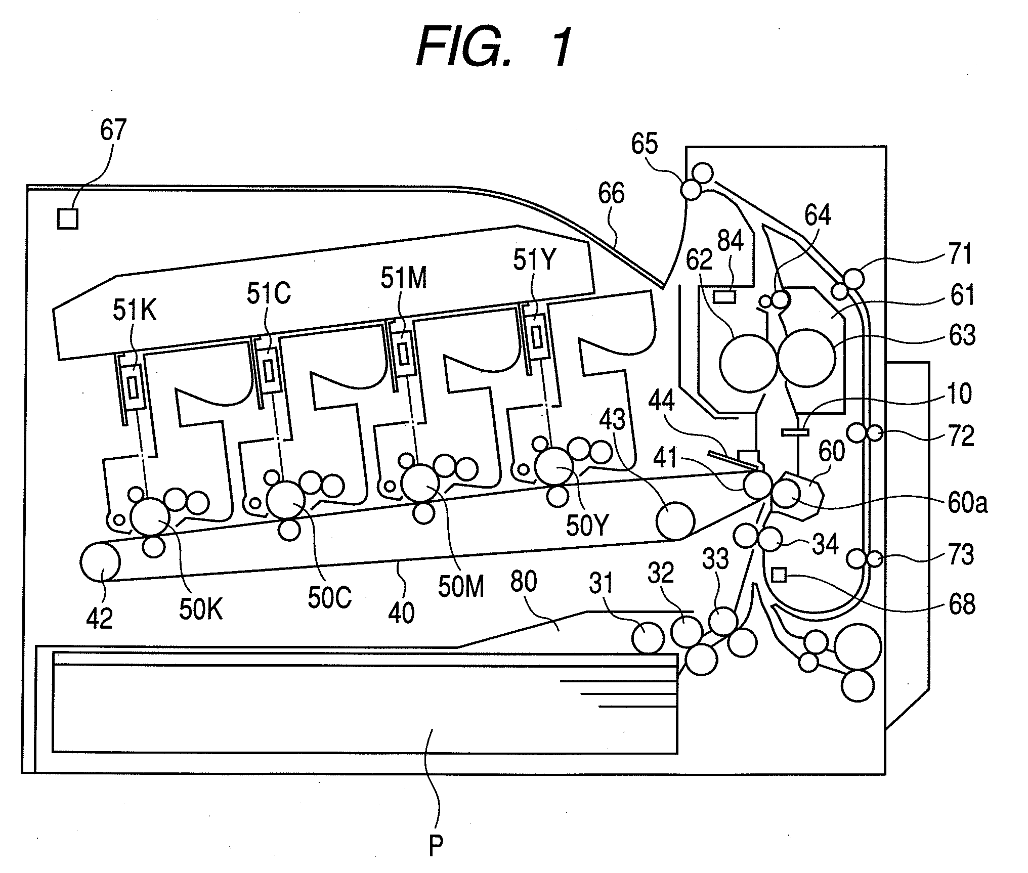
[0031]FIG. 1 is a cross section illustrating an entire structure of a color image forming apparatus according to Example 1. This apparatus is a tandem color image forming apparatus adopting an intermediate transferring member, which is an example of an electrophotographic color image forming apparatus.
[0032]An image signal is sent to an image data input portion of the color image forming apparatus directly or via a printer controller from a host computer (hereinafter referred to as host PC) connected to a network or from an operation panel. Photosensitive drums 50Y, 50M, 50C and 50K are disposed in image forming stations having color toner (developer) of yellow, magenta, cyan and black, respectively. Each of laserscanner devices 51Y, 51M, 51C and 51K corresponding to the individual colors irradiates a laser beam onto each surface of the photosensitive drums 50Y, 50M, 50C and 50K so as to form a latent image based on image data sent from a control por...
example 2
[0069]In this example, a fixing rate control is changed based on the used amount (accumulative used amount) information of the fixing unit (fixing means) and used amount (accumulated number of printed sheets) information of a transferring unit that also works as the conveying means.
[0070]A structure of the apparatus and a fixing rate control step in this example are the same as those described in Example 1, and hence detailed descriptions thereof will be omitted while the same reference numerals are used. Only the differences will be described.
[0071](8) Used Amount Detection of Transferring Unit
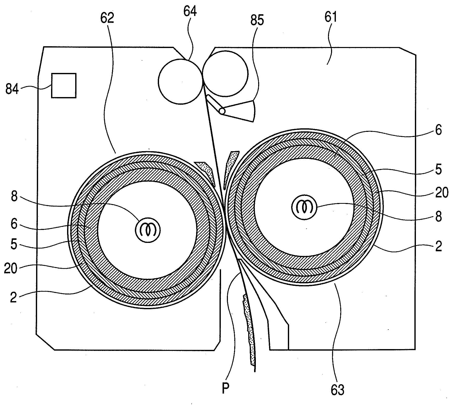
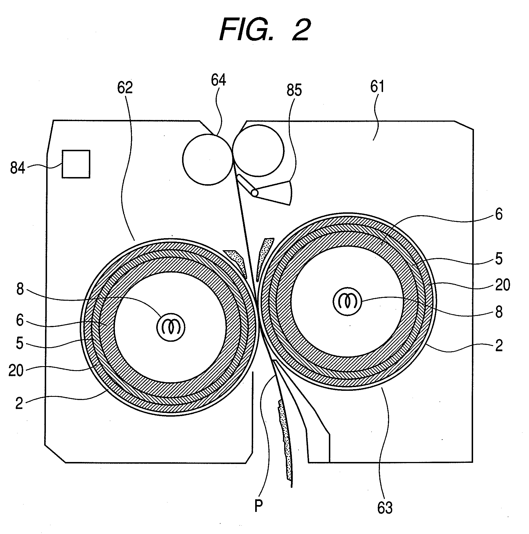
[0072]Used amount detection of the transferring unit, which is made up of a fuse (not shown) (transferring unit newness detecting means) for newness detection for detecting that a transferring unit including the secondary transferring roller 60a and the secondary transferring portion 60 is a new, is performed similarly to the used amount detection of the fixing unit 61. In other words, it is ...
example 3
[0080]This example is the same as Example 1 except for changing the speed Vh and the speed Vl of the motor 81a for the fixing unit 61 that are used for the loop control according to a result of detection by the environmental sensor 67 (environment detecting means) disposed in the apparatus main body. Therefore, the same reference numerals are used, and only the difference will be described.
[0082]In this example, similarly to Example 1, it is controlled so that Vh (higher motor rotation number) and Vl (lower motor rotation number) are switched based on a detection result of the loop sensor 10. In this embodiment, as given in Equations (5) and (6) below, Vh and Vl are decided based on the accumulated number of printed sheets x of the fixing unit 61 stored in the memory in the main body and a temperature result t (degrees centigrade) of the environmental sensor 67.
Vh=f(x,t)=−2E−06x3+0.0006x2−0.0617x+(t−23×0.03...
PUM
Abstract
An image forming apparatus is provided, which prevents occurrence of conveying malfunction or image failure due to variation of conveying speed caused by endurance of a fixing unit or a conveying unit, variation of using environment, or a type of a recording material. The image forming apparatus includes: a fixing unit for heating and fixing a toner image on a recording sheet (P); a secondary transferring portion for conveying the recording sheet (P) to the fixing unit; a loop sensor for detecting a degree of a loop of the recording sheet (P) generated according to a speed difference between a conveying speed of the fixing unit and a conveying speed of the secondary transferring portion; a CPU for controlling the conveying speed of the fixing unit; a fixing deliver sensor for detecting a used amount of the fixing unit; and an EEPROM for storing information on the used amount of the fixing unit detected by the fixing deliver sensor. The CPU controls the conveying speed of the fixing unit based on the information of the used amount of the fixing unit stored in the EEPROM and a detection result of the loop sensor.
Description
[0001]This application is a continuation of International Application No. PCT / JP2008 / 066014 filed on Aug. 29, 2008, which claims the benefit of Japanese Patent Application No. 2007-222570 filed on Aug. 29, 2007.BACKGROUND OF THE INVENTION[0002]1. Field of the Invention[0003]The present invention relates to an image forming apparatus, in particular, a controlling method used in an image forming apparatus that electrophotographically forms images and fixes the formed image onto a recording material.[0004]2. Description of the Related Art[0005]In a conventional image forming apparatus, a toner image on an image bearing member is transferred onto a recording material by transferring means such as a transferring roller and the recording material is led via a conveyance guide to a nip portion of a fixing portion, which fixes the toner image. However, there may be a state in which a rear end portion of the recording material has not passed through the transferring portion when a leading en...
Claims
Application Information
Patent Timeline
Application Date:The date an application was filed.
Publication Date:The date a patent or application was officially published.
First Publication Date:The earliest publication date of a patent with the same application number.
Issue Date:Publication date of the patent grant document.
PCT Entry Date:The Entry date of PCT National Phase.
Estimated Expiry Date:The statutory expiry date of a patent right according to the Patent Law, and it is the longest term of protection that the patent right can achieve without the termination of the patent right due to other reasons(Term extension factor has been taken into account ).
Invalid Date:Actual expiry date is based on effective date or publication date of legal transaction data of invalid patent.
