
Opportunistic uplink scheduling

a technology of uplink transmission and scheduling, applied in the field of wireless communications, can solve the problems of inefficiency and inability to sustainably rate, and achieve the effect of facilitating uplink transmission scheduling

Active Publication Date: 2009-05-21
QUALCOMM INC
View PDF43 Cites 25 Cited by
  • Summary
  • Abstract
  • Description
  • Claims
  • Application Information

AI Technical Summary

Benefits of technology

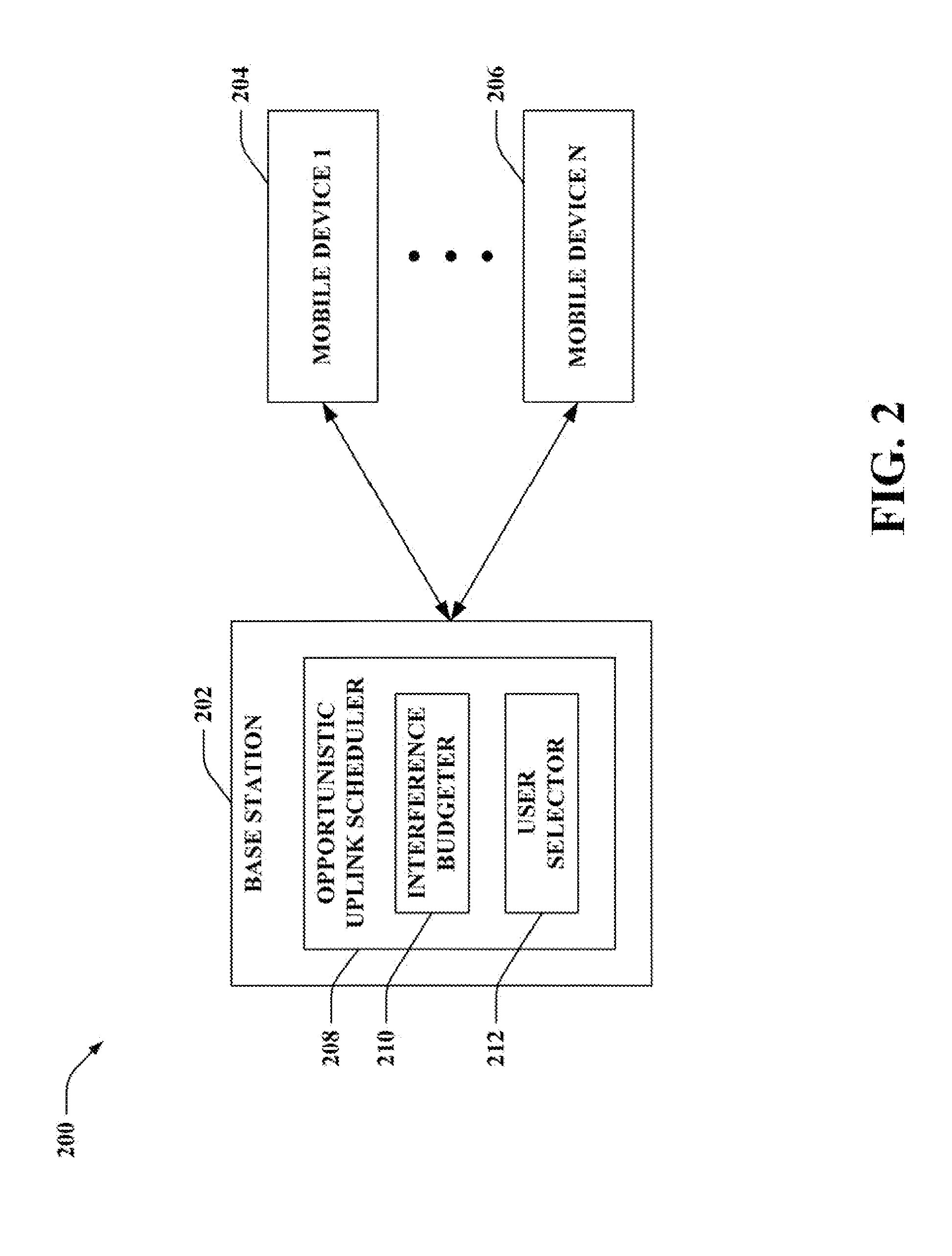
[0011]According to related aspects, a method that facilitates scheduling uplink transmissions in a communication network including a first base station that includes a first sector employing static loading offset levels is described herein. The method can include broadcasting a first loading factor based on at least a first loading offset level utilized to evaluate a path loss ratio related to a first channel that includes a first frequency bandwidth. The method can further include broadcasting a second loading factor based on at least a second loading offset level utilized to evaluate a path loss ratio related to a second channel that includes a second frequency bandwidth, the first loading offset level and the second loading offset level differ by at least 0.5 dB. Moreover, the method can comprise receiving channel quality reports from one or more mobile devices pertaining to the evaluated path loss ratios. Additionally, the method can include scheduling a first mobile device for uplink transmission on the first channel based on the channel quality reports. The method can also include scheduling a second mobile device for uplink transmission on the second channel based on the channel quality reports. Further, the method can include transmitting assignments to the first mobile device and the second mobile device related to the scheduled uplink transmissions.

Problems solved by technology

Due to the existence of inter and intra cell interference, sustainable rates can introduce inefficiencies since such sustainable rates may not be the optimal achievable rates for the users.

Method used


Image

  • Opportunistic uplink scheduling
  • Opportunistic uplink scheduling
  • Opportunistic uplink scheduling

Examples


Embodiment Construction

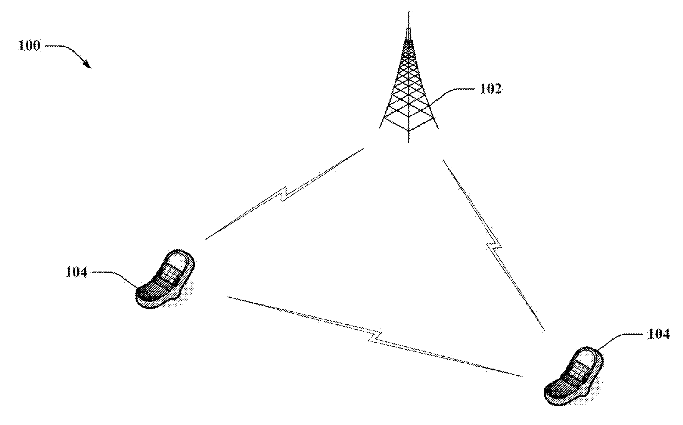
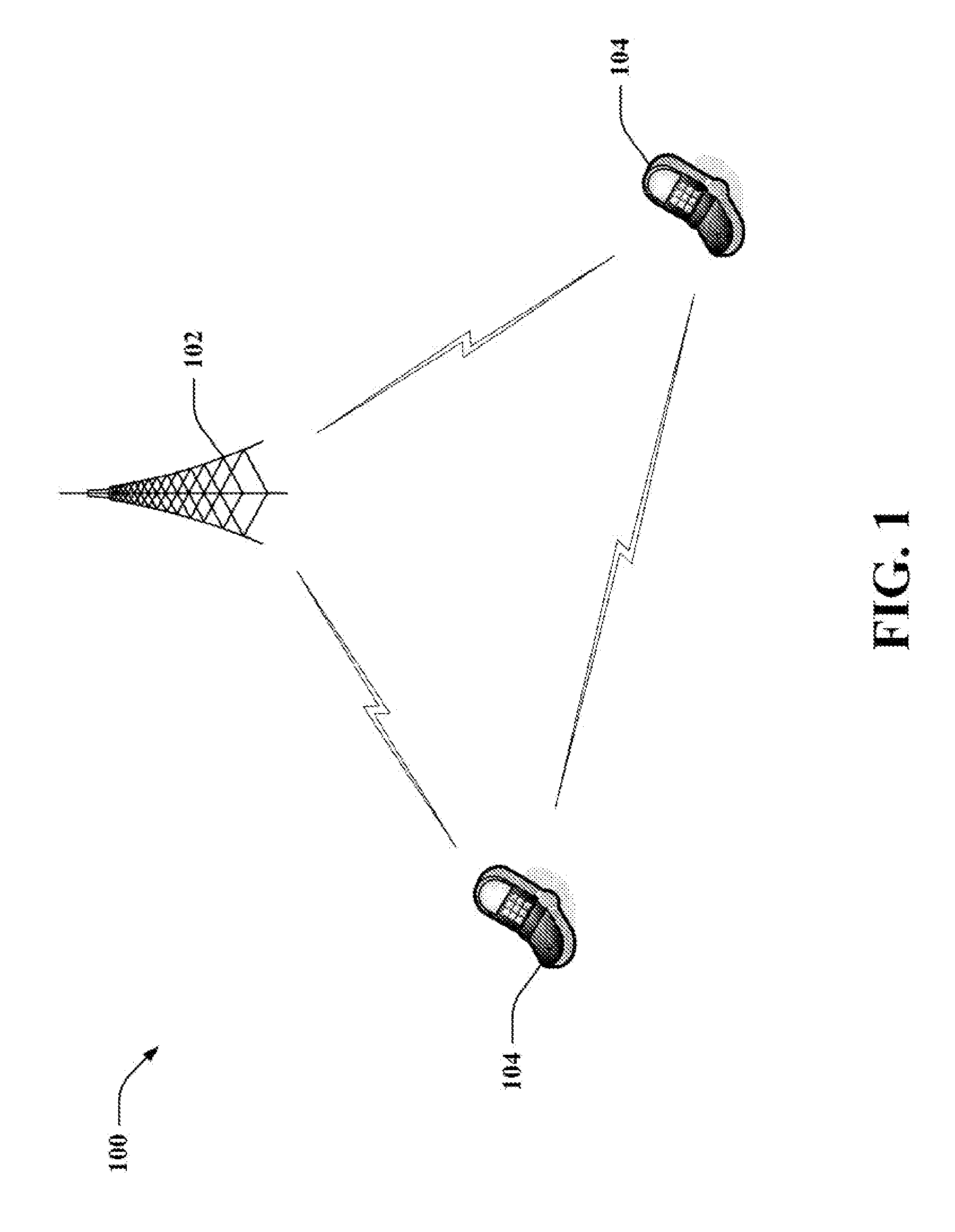
[0043]Various embodiments are now described with reference to the drawings, wherein like reference numerals are used to refer to like elements throughout. In the following description, for purposes of explanation, numerous specific details are set forth in order to provide a thorough understanding of one or more embodiments. It may be evident, however, that such embodiment(s) may be practiced without these specific details. In other instances, well-known structures and devices are shown in block diagram form in order to facilitate describing one or more embodiments.

[0044]As used in this application, the terms “component,”“module,”“system,” and the like are intended to refer to a computer-related entity, either hardware, firmware, a combination of hardware and software, software, or software in execution. For example, a component may be, but is not limited to being, a process running on a processor, a processor, an object, an executable, a thread of execution, a program, and / or a com...


PUM


Abstract

Systems and methodologies are described that facilitate scheduling uplink transmissions. For instance, a time sharing scheme can be utilized such that differing mobile devices can be scheduled to transmit during differing time slots; however, it is also contemplated that a static scheme can be employed. Pursuant to an illustration, an interference budget can be combined with a time varying weighting factor associated with a base station; the weighting factor can be predefined and / or adaptively adjusted (e.g., based upon a load balancing mechanism). Moreover, the weighted interference budget can be leveraged for selecting mobile devices for uplink transmission (e.g., based at least in part upon path loss ratios of the mobile devices). Further, disparate interference budgets can be utilized by differing channels of a sector at a particular time. Also, for example, a base station can assign a loading factor to be utilized by wireless terminal(s) for generating channel quality report(s).

Description

CROSS-REFERENCE TO RELATED APPLICATIONS[0001]This application is related to co-pending U.S. patent application Ser. No. ______, entitled “OPPORTUNISTIC UPLINK SCHEDULING” (Atty. Docket No. 061792U1), co-pending U.S. patent application Ser. No. ______, entitled “OPPORTUNISTIC UPLINK SCHEDULING” (Atty. Docket No. 061792U2), and co-pending U.S. patent application Ser. No. ______, entitled “OPPORTUNISTIC UPLINK SCHEDULING” (Atty. Docket No. 061792U4), which were each filed on the same day as the subject application.BACKGROUND[0002]I. Field[0003]The following description relates generally to wireless communications, and more particularly to uplink scheduling in wireless communication systems.[0004]II. Background[0005]Wireless communication systems are widely deployed to provide various types of communication; for instance, voice and / or data can be provided via such wireless communication systems. A typical wireless communication system, or network, can provide multiple users access to on...

Claims


Application Information

Patent Timeline
IPC IPC(8): H04Q7/20
CPCH04W72/085H04W72/0406H04W72/20H04W72/542
Inventor WU, XINZHOURANGAN, SUNDEEPHANDE, PRASHANTHDAS, ARNABLI, JUNYI
Owner QUALCOMM INC
Learn More