Use of a device to join the parts of a model designed for use in tests in a wind tunnel and the corresponding device

Inactive Publication Date: 2009-05-28
AIRBUS OPERATIONS SL
View PDF3 Cites 4 Cited by
  • Summary
  • Abstract
  • Description
  • Claims
  • Application Information

AI Technical Summary

Problems solved by technology

When dealing with the models, the wind tunnels prove quite narrow for the assemblers, and this makes the operations to be carried out more difficult.
The test is not a continuous process, in other words it is neither possible nor desirable to test all combinati

Method used


Image

  • Use of a device to join the parts of a model designed for use in tests in a wind tunnel and the corresponding device
  • Use of a device to join the parts of a model designed for use in tests in a wind tunnel and the corresponding device
  • Use of a device to join the parts of a model designed for use in tests in a wind tunnel and the corresponding device

Examples


Embodiment Construction

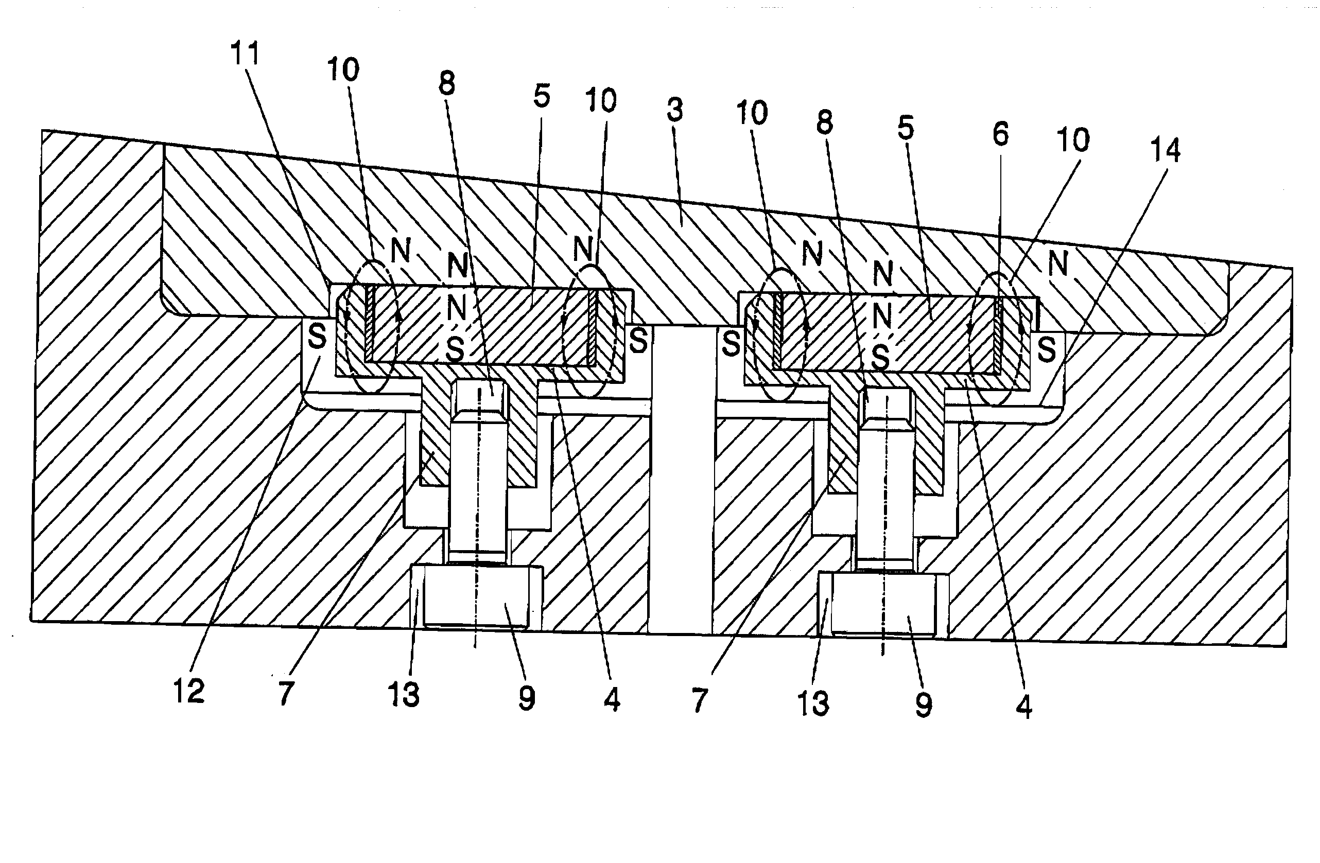
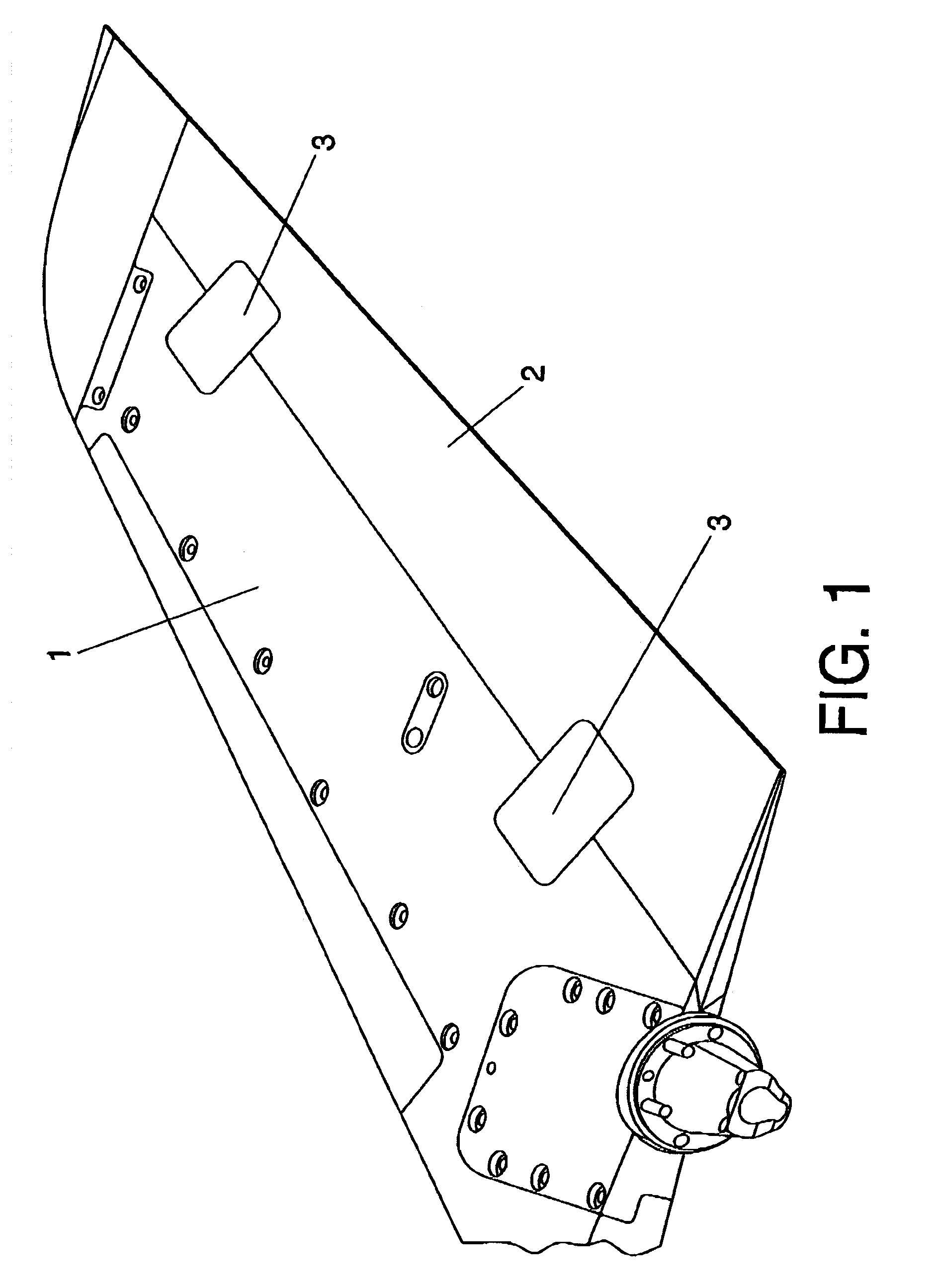
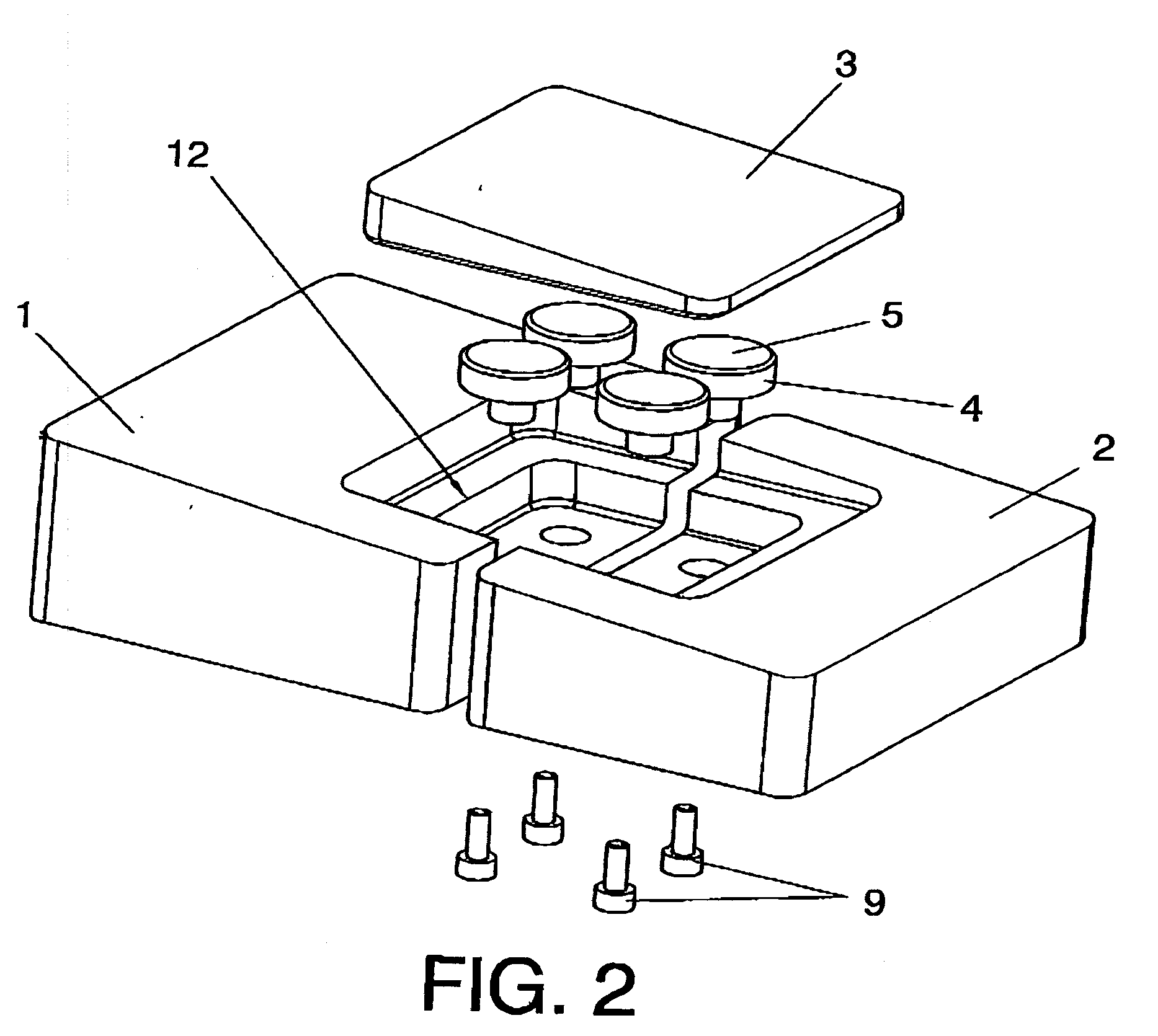
[0011]In order to resolve any inconvenience caused and to achieve the objectives indicated above, the invention provides for the innovative use of a device to join the parts of a model designed for use in tests in a wind tunnel. The parts of the model are made of ferromagnetic material and designed in such a way that the parts are joined by a device consisting of at least one magnet.

[0012]To this end, the device can be adapted by incorporating a means of attaching it to one of the parts to be connected to it, including at least one magnet to connect it to one of the other parts.

[0013]As a result, the invention allows magnets to be used to join the metal parts used in the models together, something which has not been achieved to date, due to the characteristics of the models in question, such as their small size, the number of instruments fitted inside, etc., and factors inherent to the test, such as the large aerodynamic loads produced, the speed of dismantling between configuration...


PUM

PropertyMeasurementUnit
Areaaaaaaaaaaa

Abstract

The model is designed in such a way that the parts are joined by specially adapted magnets. This adaptation involves the use of at least one shell (4) made from ferromagnetic material, open on one side, and equipped with a means of attaching itself to one of the parts to be joined (2), which will house and hold a magnet in place in its interior (5), and whose open side will be covered by another of the parts to be joined (3), to create a continuous magnetic field with closed (10) loops around the shell (14), ensuring that only the magnetised area of the other part to be joined (2) will cover the open side of the shell, creating the link between the parts. The use of the magnets optimises the time required for the assembly of the model and changes to its configuration, in order to carry out different tests, thereby increasing the productivity of the test.

Description

PURPOSE OF THE INVENTION[0001]The invention is suited to use in models comprising ferromagnetic parts, and its purpose is to allow magnets to be used to join the parts of the model, thereby providing a design for the model and the magnets that allows the link to be created.[0002]The invention also refers to a device that joins the parts of the model together using magnets.[0003]The invention can be used in any sector of an industry where models need to be made and subjected to aerodynamic tests, particularly the aeronautics industry.[0004]The invention considerably reduces the assembly time required for the model, by avoiding the use of nuts and bolts usually required to secure the different parts that comprise the models used to carry out tests in wind tunnels.BACKGROUND OF THE INVENTION[0005]The use of aeronautic models when carrying out tests in a wind tunnel is known in the state of the art, where the models are contained in boxes, and once received the assemblers remove all of ...

Claims


Application Information

Patent Timeline
IPC IPC(8): B23P19/04
CPCY10T29/53G01M9/08
Inventor DE PABLO PEREZ, JESUS
Owner AIRBUS OPERATIONS SL
Why Eureka
Try Eureka