Vehicle propelled by muscle power, in particular step scooter

a technology of muscle power and vehicles, applied in vehicles, bicycles, cycles, etc., can solve the problems of reducing the efficiency of force transmission, reducing the efficiency of step frequency, and affecting the performance of vehicles propelled by muscle power, so as to reduce the disadvantages of the state of the art

Inactive Publication Date: 2009-05-28
GRADITECH ENTWICKLUNGS
View PDF15 Cites 8 Cited by
  • Summary
  • Abstract
  • Description
  • Claims
  • Application Information

AI Technical Summary

Benefits of technology

[0007]There may thus be a need to create a vehicle propelled by muscle...

Problems solved by technology

The disadvantage of such vehicles propelled by muscle power according to the state of the art is the fact that as a rule, the transmission ratio between vehicle path and step path across the entire step surface stroke is constant or approximately constant.
As a consequence, such vehicles require a gear shift for a practicable speed and load range (for example different inclines), because otherwise the step frequency becomes too large, for example at high speeds, or because certain inclines can otherwise not be handled or can only be handled with difficulty.
For the most part, commercially available gear shifts are technically extensive, must be serviced by the user (lubricated, adjusted) and basically reduce the efficiency of the force transmission, which represents a particularly profound disadvantage with vehicles propelled by muscle.
The disadvantage of this drive and of other exemplary embodiments in which the driving element is guided about a cam disk is the fact that the cam disk can undertake maximally approximately...

Method used


Image

  • Vehicle propelled by muscle power, in particular step scooter
  • Vehicle propelled by muscle power, in particular step scooter
  • Vehicle propelled by muscle power, in particular step scooter

Examples


Embodiment Construction

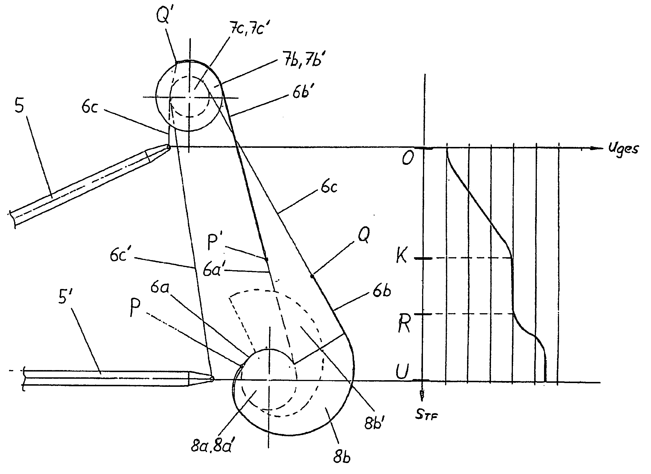
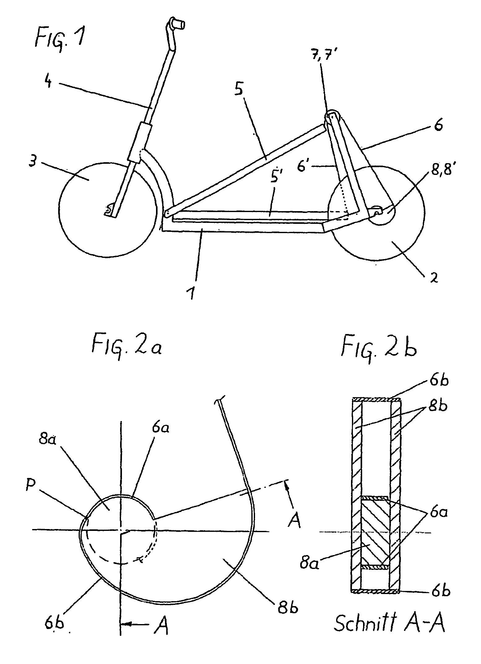
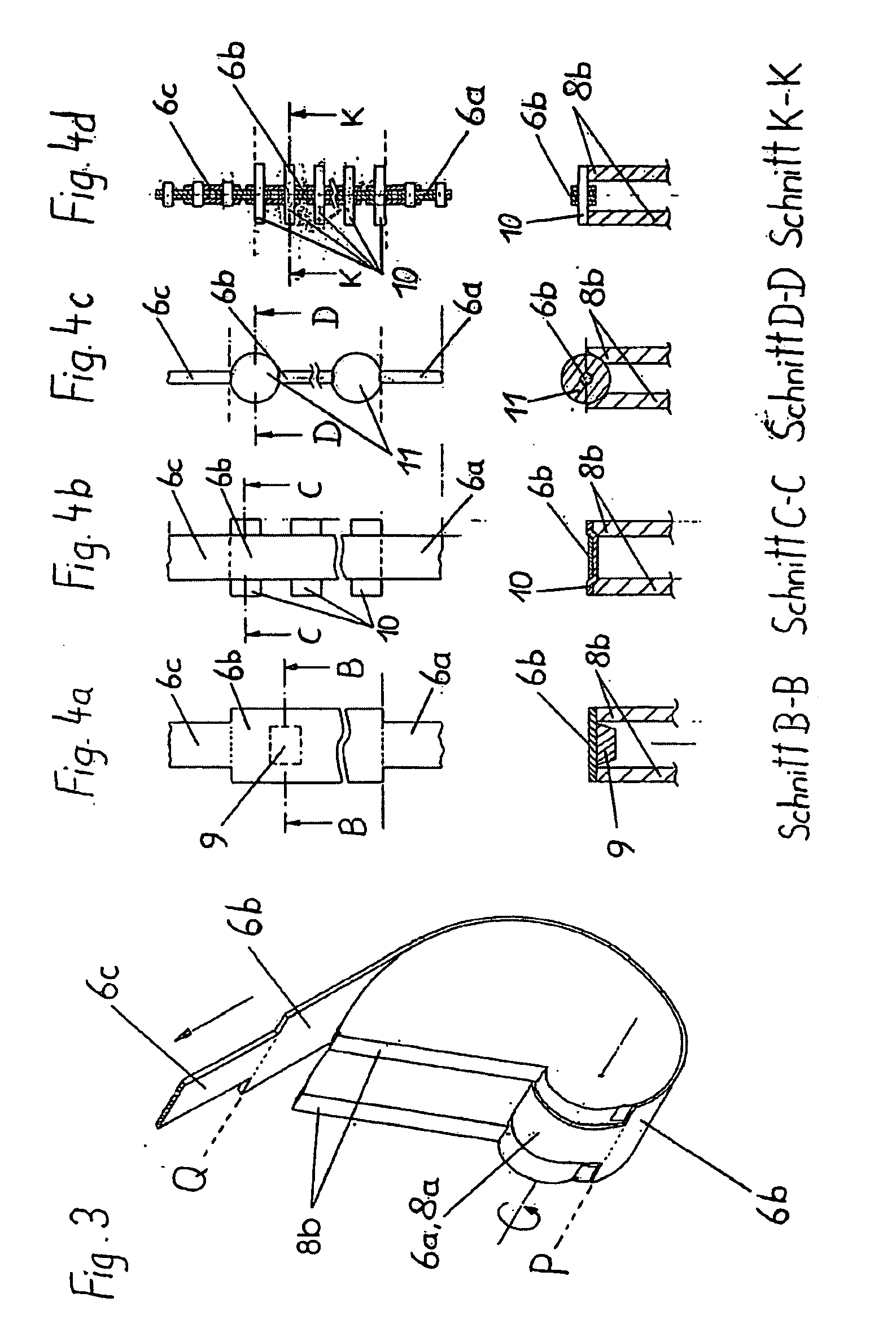
[0061]The vehicle propelled by muscle power diagrammatically illustrated in FIG. 1 represents an exemplary embodiment of a step scooter with two step surfaces 5, 5′, which are designed as levers. A vehicle frame 1, two step surfaces 5, 5′ connected to the vehicle frame 1 in a jointed manner (gelenkig), a driving wheel 2 as well as a further wheel 3, which is connected to the vehicle frame 1 in a jointed manner via a device for steering 4, are shown. In exemplary embodiments, the vehicles propelled by muscle power of this species can also comprise a plurality of driving wheels 2 or additional wheels 3. Design alternatives for more than one person are also possible. In the shown exemplary embodiment, the driving element 6 is guided from the step surface 5 shown in the upper initial position of the step surface stroke via a deflection roller 7, which is connected to the vehicle frame 1, to the drive shaft 8, which is coupled with the hub of the driving wheel 2 via a freewheeling mechan...


PUM


Abstract

Vehicle propelled by muscle power, in particular scooter, with at least one driving wheel and at least one tread surface (5, 5′) which is movable via a tread surface stroke, wherein the force transmission from the at least one tread surface (5, 5′) to the at least one driving wheel takes place by means of a driving element (6, 6′) which is guided with a nonpositive fir via a drive shaft (8, 8′) which is coupled to the driving wheel via a freewheeling mechanism, wherein the drive shaft (8, 8′) and/or preferably at least one deflecting roller (7, 7′) is/are divided into at least two axial regions (7b, 7c; 7b′, 7c′, 8a, 8b; 8a′; 8b′) with radii which differ from one another or are variable, and the driving element (6, 6′) is divided into partial sections with different cross sections which are designed in such a manner that the partial sections (6a, 6b 6c; 6a′, 6b′ 6c′) of the driving element (6, 6′) are guided within the tread surface stroke (O-U) on the respectively corresponding axial region of the drive shaft (8, 8″) and/or deflecting roller (7, 7′). As a result, the overall transmission ratio (uges) of the vehicle can be configured within the tread surface stroke (O-U) within wide limits, wherein, in particular, the drive shaft (8, 8′) which is designed according to the invention can undertake a plurality of revolutions without colliding with a driving element.

Description

FIELD OF THE INVENTION[0001]The invention relates to a vehicle propelled by muscle power, in particular step scooter (Stepproller), with at least one driving wheel and at least one step surface, which is movable via a step surface stroke, wherein the force transmission from the at least one movable step surface to the driving wheel takes place via a driving element, one end of which is coupled to the motion of the step surface and which is guided with a non-positive or positive fit via a drive shaft, which is coupled to the at least one driving wheel via a freewheeling mechanism.BACKGROUND OF THE INVENTION[0002]Exemplary embodiments of vehicles propelled by muscle power, which are driven by the driver by at least one step surface, which is movable via a step surface stroke and which also comprise a steering device, are identified as pedal mobile, scooter, see-saw scooter or lever-propelled bicycle, for example. As a rule, such vehicles are equipped with one, but in particular with t...

Claims


Application Information

Patent Timeline
IPC IPC(8): B62M1/04B62M1/24B62M1/28
CPCB62K3/002B62M1/28B62M1/24
Inventor BUCHBERGER, MARTINBUCHBERGER, PETER
Owner GRADITECH ENTWICKLUNGS
Why Eureka
Try Eureka