

Ipm type of synchronous machine
a synchronous machine and permanent magnet technology, applied in the direction of dynamo-electric machines, electrical apparatus, magnetic circuits, etc., can solve the problems of not being able to use the only possible structure, using a large amount of rare earth magnets, and being very expensive, so as to suppress the increase in the amount of magnet use, the effect of increasing the output torqu
- Summary
- Abstract
- Description
- Claims
- Application Information
AI Technical Summary
Benefits of technology
Problems solved by technology
Method used
Image

Examples
first embodiment
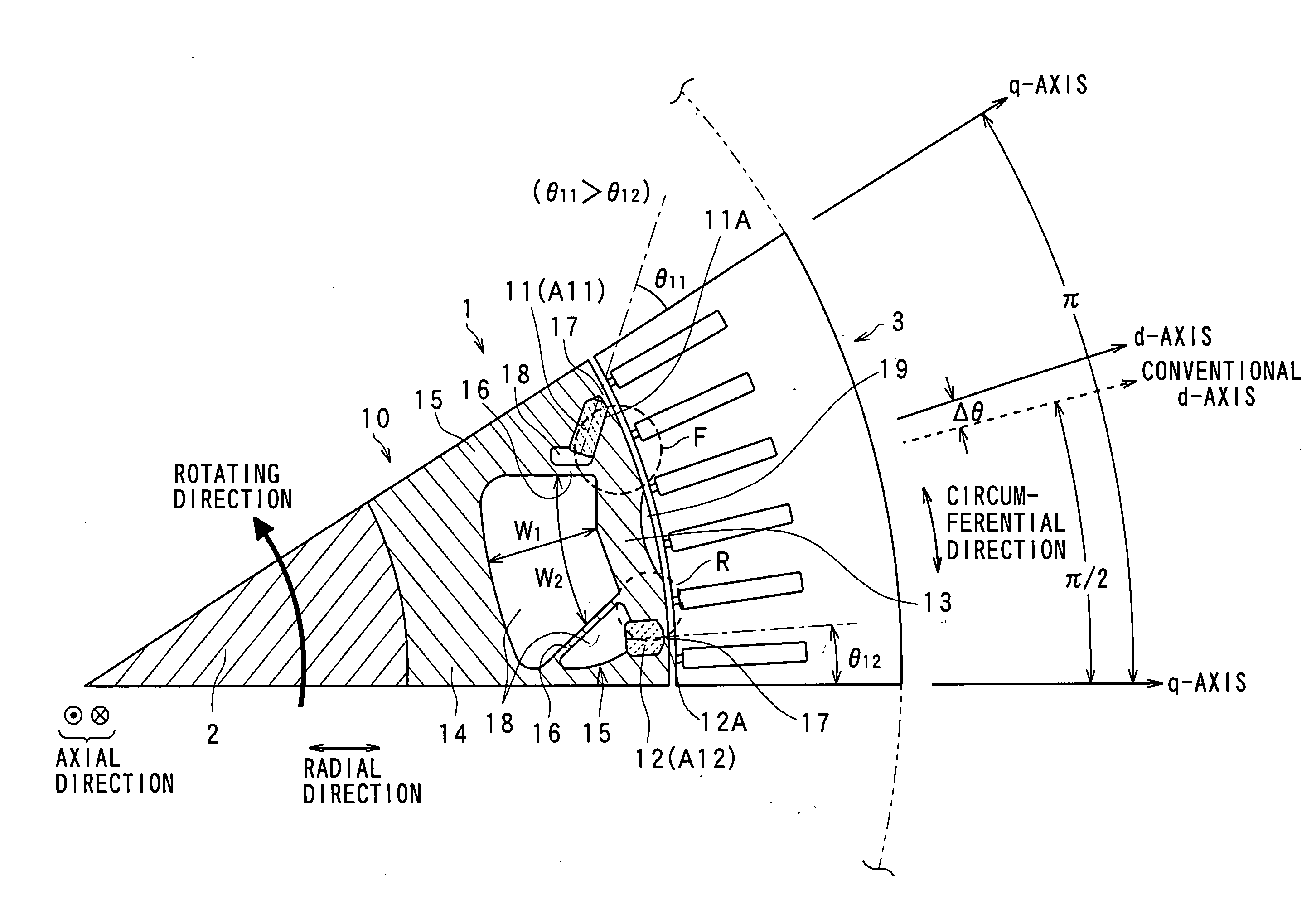
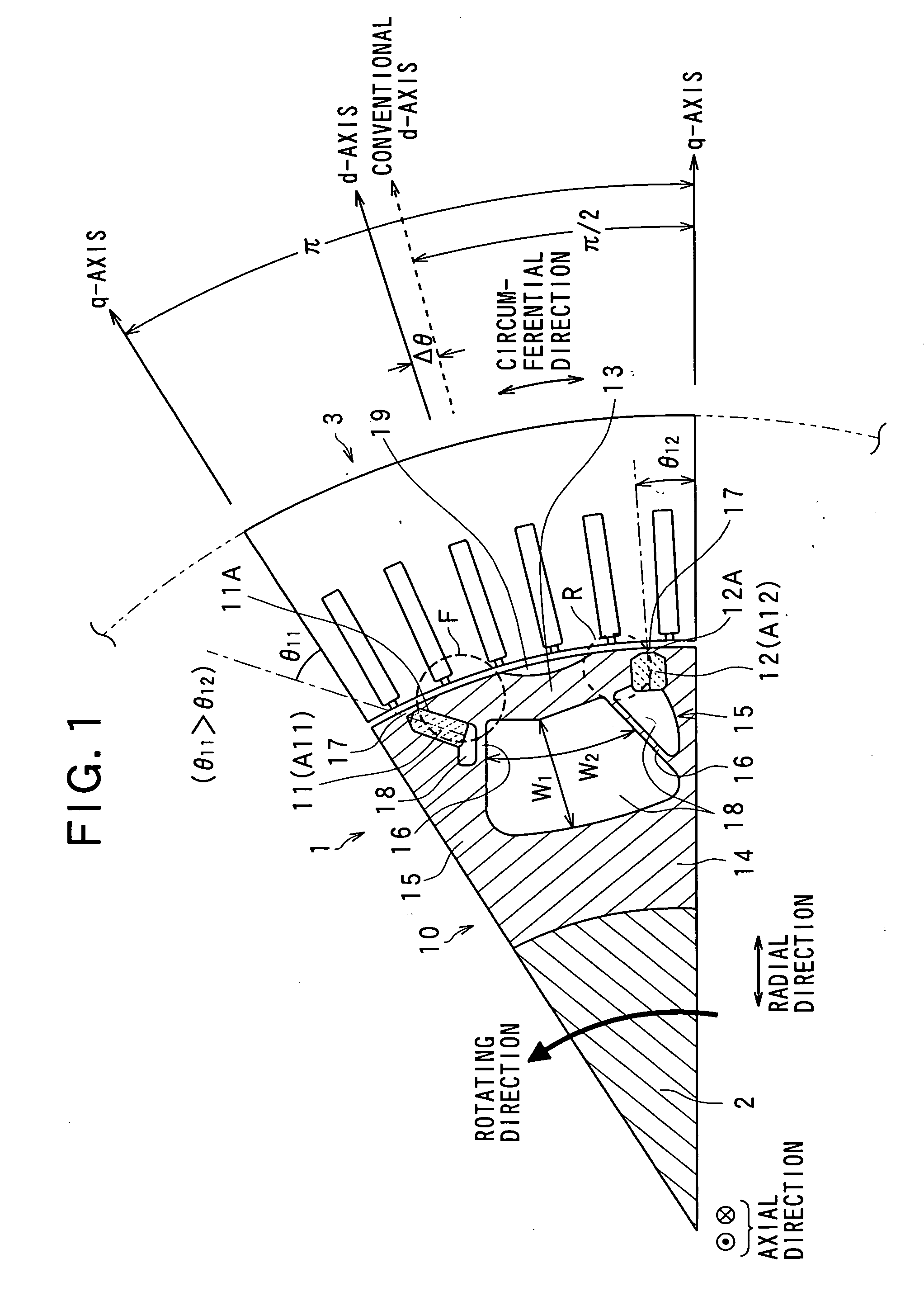
[0029]Referring to FIGS. 1-2, an interior permanent magnet (IPM) type of synchronous machine according to a first embodiment of the present invention will now be described
[0030]FIG. 1 is a partial sectional view of the rotor of the synchronous machine, which is cut in the axial direction thereof, to show the inside partial structure of the rotor.
[0031]In the structure shown in FIG. 1, there are a rotor 1, a rotation shaft 2, and a stator 3. The stator 3 is provided with a stator core with slots and tooth formed on its inner surface and a stator coil wound in the slots. Since such a stator core structure is known, its detailed description will be omitted here.
[0032]The rotor 1 is provided with a rotor core 10 made of soft magnetism material, frontal permanent magnets 11, rear permanent magnets 12, and segments made of soft magnetism material. In the present embodiment, the “frontal, front, or front side” and “rear or rear side” are defined in a rotating direction (a counter clockwise...
second embodiment
[0069]Referring to FIG. 11, a second embodiment of the synchronous machine according to the present invention will now be described. In the present embodiment and subsequent embodiment, the identical or similar elements to those in the first embodiment are given the same reference numerals for the sake of avoiding a redundant description.
[0070]FIG. 11 shows a partial sectional view of a rotor 2 according to the present embodiment. This rotor 2 is structured Into an outer rotor. In this outer rotor structure, an inter-segment / yoke non-magnetic portion 180 formed within the rotor 2 is filled with resin serving as a non-magnetic material. This filling technique allows the portion 180 itself to support the segment 13 and the permanent magnets 11 and 12, largely improving tolerability for the centrifugal force.
[0071]That is, in the outer rotor structure, it is not necessary to take it into consideration so much the tolerance for the centrifugal force, so that the rotation performance in ...
third embodiment
[0072]Referring to FIGS. 12-15, a third embodiment of the synchronous machine according to the present invention will now be described.
[0073]In the present embodiment, the rear connecting portion is removed from the structure, so that the rear end of the segment 3 in the rotating direction is separated from the side of the tip end of the rear magnetic salient pole 15, as shown in FIGS. 12 and 14.
[0074]This separation structure prevents the segment 13 from generating tension stress therein by pulling the tip and rear ends of the segment 13 in the opposite directions respectively on account of a force caused in the rotation, It is thus possible to reduce the width of the frontal connecting portion 17 in the radial direction. Moreover, the flux leakage at the rear and of the segment 13 can be reduced, because of no connecting portion thereat.
[0075]Further, as shown in FIGS. 13 and 14, the frontal and rear permanent magnets 11 and 12 are produced such that the widths of the magnets 11 a...
PUM
 Abstract
Description
Claims
Application Information