Visible imaging device with a colour filter

a technology of colour filter and imaging device, which is applied in the field of colour filtering visible imaging device, can solve the problems of inability to detect the image, the pixel size presents an optical problem and an integration problem, and the image device is becoming smaller and smaller

Inactive Publication Date: 2009-05-28
COMMISSARIAT A LENERGIE ATOMIQUE ET AUX ENERGIES ALTERNATIVES
View PDF9 Cites 27 Cited by
  • Summary
  • Abstract
  • Description
  • Claims
  • Application Information

AI Technical Summary

Problems solved by technology

Moreover, imaging devices are becoming smaller and smaller, as production processes make it possible to produce more sensors per silicon wafer.
The reduction of the pixel size presents an optical problem and an integration problem:
The optical problem is inherent to the diffraction phenomenon that appears when the size of the optical elements approaches that of the wavelength.
Thus, the microlenses, due to the reduction in their size, no longer form actual images of the pupil of the main optics on the plane of the sensor, but instead form light spots with diffraction lobes that cannot be superimposed precisely at the detection zones.
The integration problem lies in the difficulty of producing a “Bayer filter” due to the need to produce increasingly precise lithographic patterns in order to juxtapose the various materials constituting said filter.

Method used


Image

  • Visible imaging device with a colour filter
  • Visible imaging device with a colour filter
  • Visible imaging device with a colour filter

Examples


example embodiment

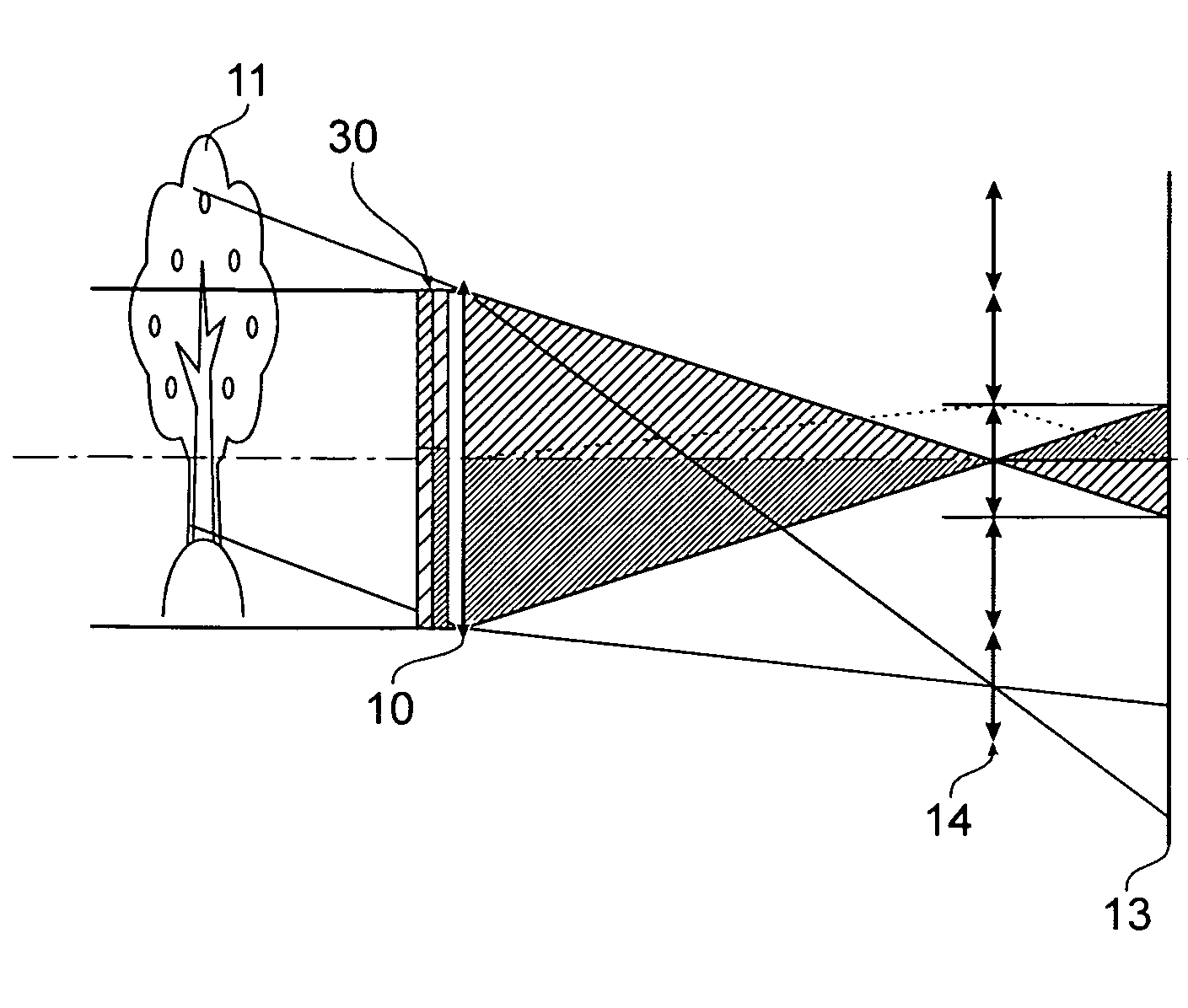
[0043]The colour filter structure can be produced on or in the vicinity of an IR (Infrared) filter or an OLPF (Optical Low pass Filter), for example, described in the document referenced [1], used to remove the ripple effect due to the pixel discretisation, in which said filter is arranged near the main optics 10, advantageously in the main optics 10.

[0044]The colour filter can be produced by any known conventional optics process, for example by deposition of organic coloured materials, by means of a stencil, on a transparent plate with an optically planar surface. It can also be produced by localized deposits of multiple optical layers functioning by light interference.

[0045]In both cases, the colour filter is produced by a collective process, starting with a large substrate (at the base), an IR or OLPF filter on which the photolithographic resin is deposited, which is exposed once through a mask (conventional lithography process) and developed, allowing only the zones intended to ...


PUM


Abstract

A visible imaging device with a colour filter, including:main optics (10) equipped with a pupil,a sensor (13) forming a sensitive pixel array,a circuit for addressing said pixels,a microlens array (14) producing the optical conjugation between the pupil of the main optics (10) and a group of pixels of the sensor,a colour filter (30, 40),in which the colour filter (30, 40) is arranged in the vicinity of the pupil of the main optics.

Description

CROSS REFERENCE TO RELATED APPLICATIONS OR PRIORITY CLAIM[0001]This application claims priority to French Patent Application No. 07 59346, filed Nov. 27, 2007.DESCRIPTION[0002]1. Technical Field[0003]The invention relates to a visible imaging device with a colour filter.[0004]2. Prior Art[0005]The field of visible imaging devices is growing rapidly. Thus, numerous multi-use portable telephones with a photographic apparatus, i.e. a camera, function are currently being placed on the market. This is a very competitive field, which requires production costs to be reduced. Moreover, imaging devices are becoming smaller and smaller, as production processes make it possible to produce more sensors per silicon wafer. Increasing numbers of pixels (or image elements) are thus provided for each sensor. A pixel corresponds to a basic pattern including the sensitive zone and the spaces reserved for interconnections or electronic circuits. Imaging devices with more than 3 million pixels (2000×150...

Claims


Application Information

Patent Timeline
Patent Type & Authority Applications(United States)
IPC IPC(8): H04N5/335
CPCG02B3/0056H04N9/045G02B13/001G02B5/201H04N25/134
Inventor GIDON, SERGE
Owner COMMISSARIAT A LENERGIE ATOMIQUE ET AUX ENERGIES ALTERNATIVES
Why Eureka
Try Eureka