Impact resistant aircraft fuselage

a fuselage and impact resistance technology, applied in the direction of fuselages, sustainable transportation, transportation and packaging, etc., can solve the problems of many closed cells remaining in the residual body, and achieve the effect of increasing the resistance to damage and sufficient residual torsional strength

Active Publication Date: 2009-06-04
AIRBUS OPERATIONS SL
View PDF10 Cites 27 Cited by
  • Summary
  • Abstract
  • Description
  • Claims
  • Application Information

AI Technical Summary

Benefits of technology

[0007]The present invention develops a rear fuselage of an aircraft comprising a double resistant shell joined by means of radial ribs. The fuselage skin of the aircraft in turn comprises multiple closed cells, such that a possible damage sectioning the fuselage will still residually leave many closed cells. As the torsional strength of a section is proportional to the area enclosed by the closed cells, sufficient residual torsional strength is ens

Problems solved by technology

The fuselage skin of the aircraft in turn comprises multiple closed cells, such that a

Method used


Image

  • Impact resistant aircraft fuselage
  • Impact resistant aircraft fuselage
  • Impact resistant aircraft fuselage

Examples


Embodiment Construction

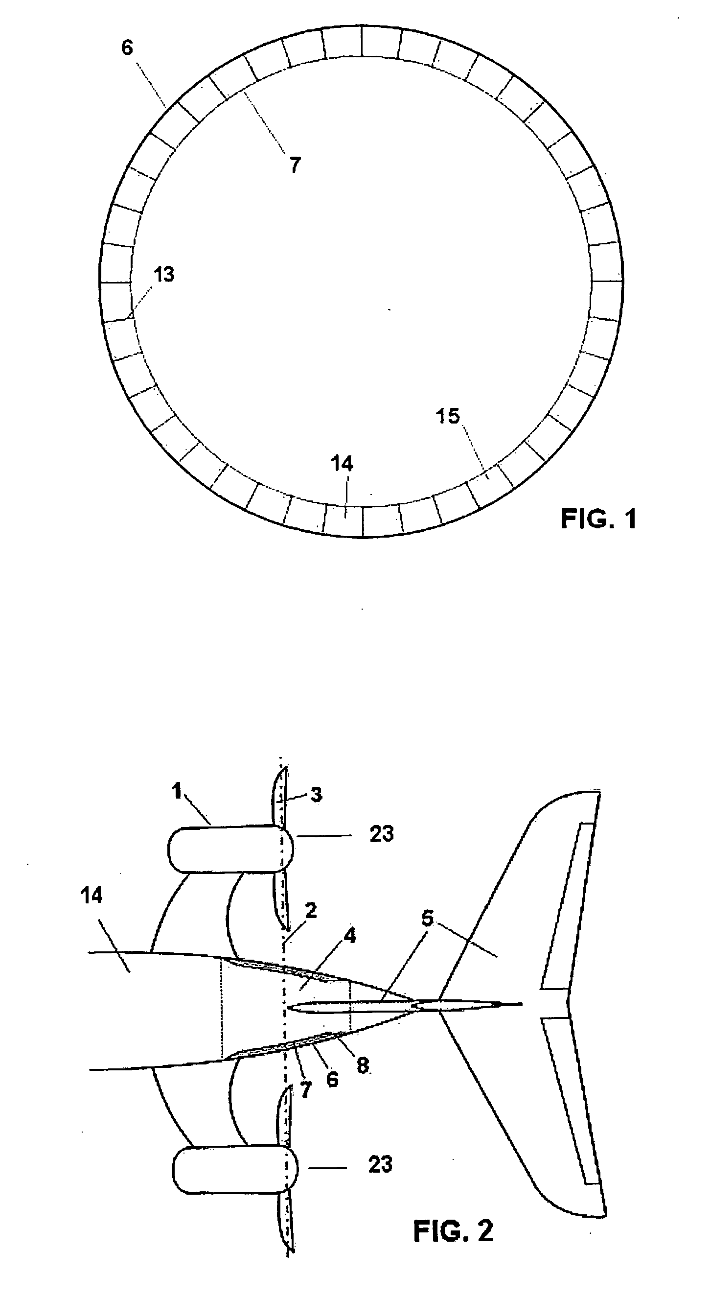
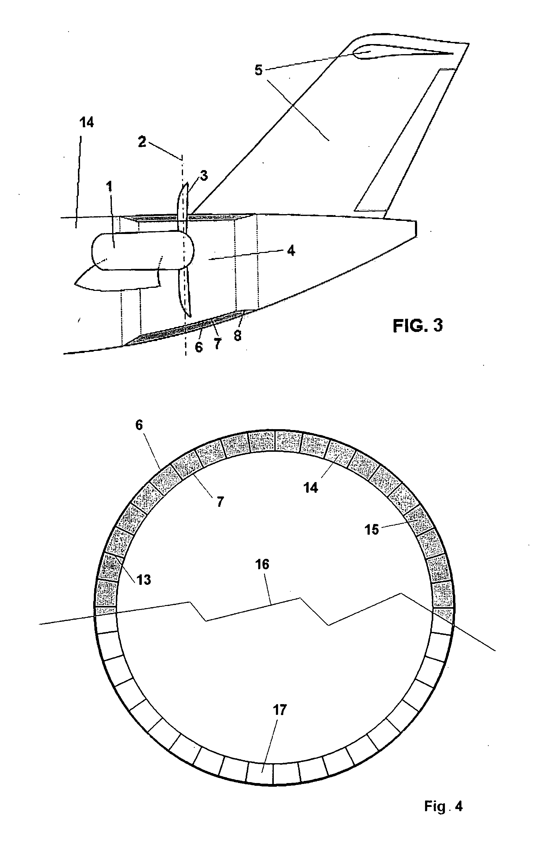
[0014]According to the invention (see FIG. 1), the rear fuselage 4 of an aircraft comprises an outer casing or skin 6 and an inner casing or skin 7, both skins 6 and 7 being joined by means of radial elements 13. The cells 14 resulting from the previous configuration of fuselage 4 will preferably be filled with a not very dense resistant material 15, such that this filling of material 15 has the effect of preventing the local buckling of the cells 14 of the structure, thus stabilizing the thin-walled multi-cell structure of the fuselage 4.

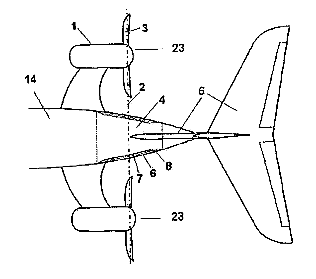
[0015]The propeller engines 1 of the aircraft can be attached to the fuselage 14 of the aircraft (as shown in FIG. 2) or to another place. Said Figure shows the plane 2 of the propellers 23, the blades 3 of a propeller 23, the empennage 5 of the aircraft and the rear fuselage area 4 which can be damaged, the rear fuselage 4 comprising an outer skin 6, an inner skin 7 and a transition area 8 between the fuselage 14 and the rear fuselage 4.

[0016]As s...


PUM


Abstract

The invention relates to a structural configuration of the rear fuselage (4) of an aircraft with propeller engines (1) comprising propellers (23) formed in turn by blades (3), the mentioned propeller engines (1) being located at the rear part of the aircraft and the empennage (5) of the aircraft in turn being located behind the plane of the propellers (23), characterized in that the structural configuration of the rear fuselage (4) comprises an outer skin (6) and an inner skin (7), both skins (6, 7) being joined by means of radial elements (13) configuring cells (14), such that the obtained structural configuration maximizes the torsional strength of the rear fuselage (4) of the aircraft in the event of damage of the mentioned rear fuselage (4) due to the detachment of one of the blades (3) of the propeller engines (1).

Description

FIELD OF THE INVENTION[0001]The present invention relates to an impact resistant fuselage for aircraft with propeller engines located at the rear part and with the empennage located behind the plane of the propellers.BACKGROUND OF THE INVENTION[0002]A failure in the engine causing the detachment of one of the blades of the propeller can impact against the rear fuselage at high speed, sectioning it. In this emergency condition, the aircraft operates with only one engine generating a forward thrust, outside the plane of symmetry of the airplane. This thrust causes a yawing moment which must be balanced with a side aerodynamic force caused by the vertical stabilizer of the empennage, so that the aircraft can continue navigating stably. As the vertical stabilizer is located above the rear fuselage, this side aerodynamic force generates a torsion along the rear fuselage. If the blade impacts against the fuselage and sections it, the torsional strength of the fuselage is considerably redu...

Claims


Application Information

Patent Timeline
IPC IPC(8): B64C1/00B64D27/00
CPCB64C1/068B64C1/12Y02T50/433B64D27/08B64D27/14B64C2001/0072B64C1/0685Y02T50/40
Inventor VERDE PRECKLER, JORGE PABLO
Owner AIRBUS OPERATIONS SL
Why Eureka
Try Eureka