
Device for actuating a process valve for use in foodstuffs technology

a technology of process valve and valve stem, which is applied in the direction of lift valve, valve details, functional valve types, etc., can solve the problems of short-duration opening of one of the valve stems, unintentional actuation of the process valve by the control valve that is switched to exhaust ventilation, and loss of products, so as to prevent the installation, prevent the installation, and detect the effect of a very short period of tim

Active Publication Date: 2009-06-04
APV ROSISTA
View PDF5 Cites 3 Cited by
  • Summary
  • Abstract
  • Description
  • Claims
  • Application Information

AI Technical Summary

Benefits of technology

[0009]Accordingly it is an object of the invention to provide a device for actuating a process valve, according to the preamble of claim 1, wherein an unintentional lifting motion of one of the valve stems of the process valve to be actuated, caused by the exhaust air from another control valve arrangement of the device for actuating the process valve, is prevented.

Problems solved by technology

This can give rise to the disadvantage that the venting of air from one control valve via the common exhaust-air line causes compressed air to come in via another control valve that has connected the exhaust-air line to the cylinder chamber normally actuated by it.
Although, in this position, the exhaust air from the cylinder chamber is intended to escape outwards, the compressed air present in the common exhaust-air line can result in unintentional actuation of the process valve by the control valve that is switched to exhaust ventilation.
Unintentional, short-duration opening of one of the valve stems can be effected as a result.
This is particularly undesirable in foodstuffs technology, and can constitute a safety-relevant hazard for the quality of the foodstuff, since, for example, contamination of the leakage cavity can occur as a result.
A further resultant disadvantage is that there can be a loss of product, owing to the unintentional lifting motion of one of the valve stems.

Method used


Image

  • Device for actuating a process valve for use in foodstuffs technology
  • Device for actuating a process valve for use in foodstuffs technology
  • Device for actuating a process valve for use in foodstuffs technology

Examples


Embodiment Construction

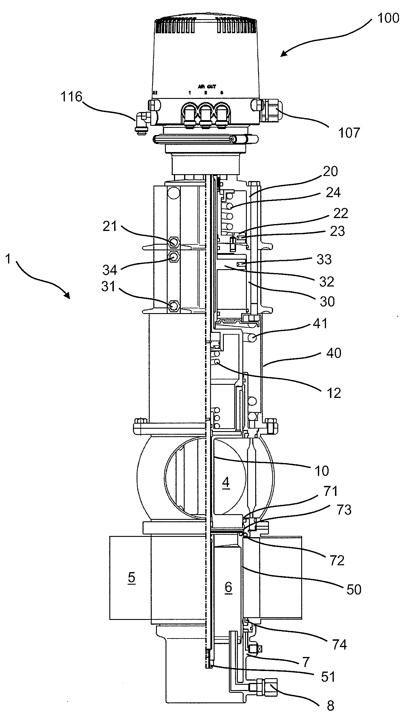
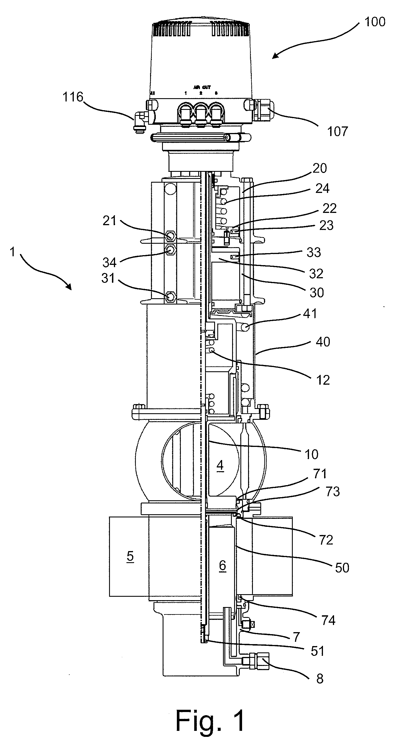
[0144]FIG. 1 is the double-seat valve 1 of FIG. 2 in the closed position, and comprising a control unit, according to the invention, arranged in a housing having a cover.

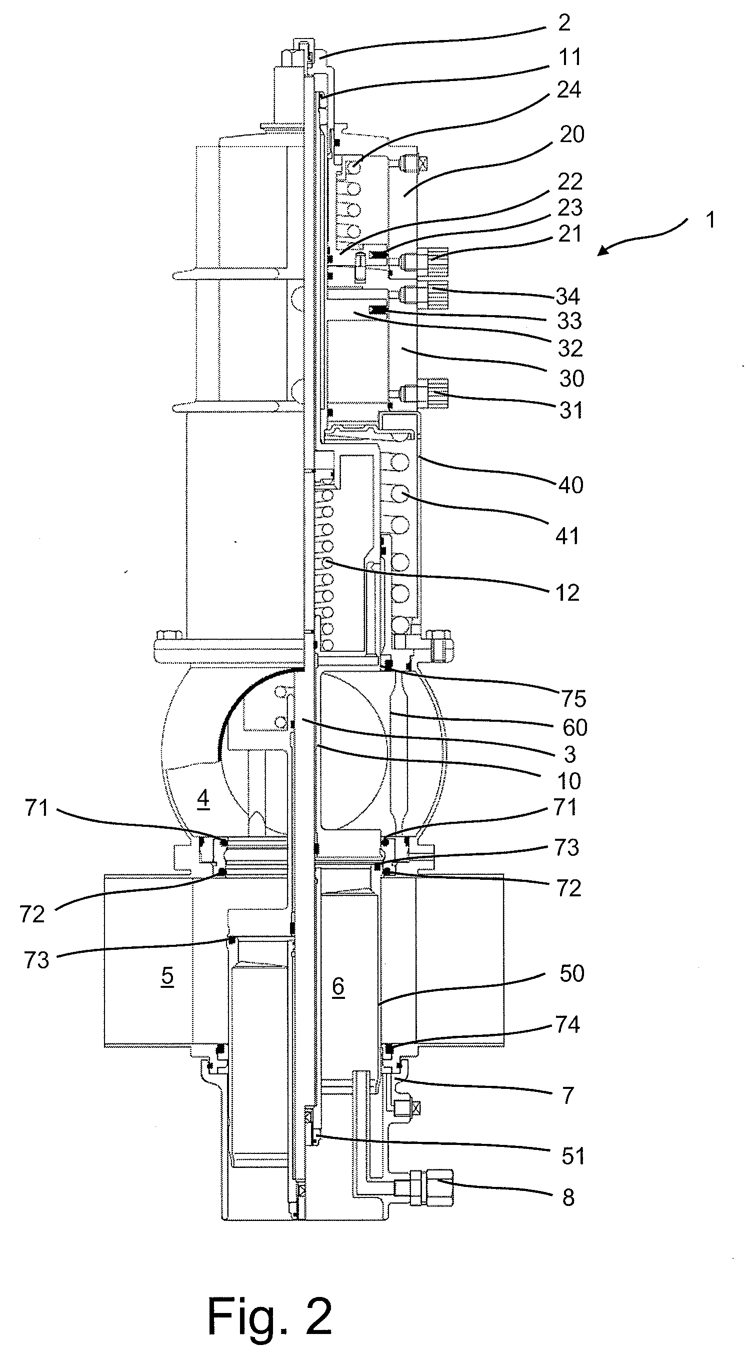
[0145]FIG. 2 is a cross-sectional view of the double-seat valve represented in FIG. 1, the control unit shown in FIG. 1 not being represented, for reasons of clarity. The double-seat valve represented can be connected in known manner to a device, according to the invention, for actuating the process valve. A comprehensive description of a double-seat valve can be found in the product information sheet for the double-seat valve DELTA DA3+ of the present applicant, the content of which description is included in the present application by reference.

[0146]The stop screw 2 serves to position the lower valve stem 50 and the optical position indicator. The double-seat valve further has a connecting rod 3. Displaceably arranged in the cylinder 20 is a piston 22, which is sealed in respect of the cylinder 20 by means of a p...


PUM


Abstract

The invention relates to a device (100) for actuating a process valve that has a first cylinder and a second cylinder, comprising at least one first control valve arrangement (102) that has at least a connector for a line to the first cylinder of the double-seat valve, an intake-air connector and an exhaust-air connector, and comprising a second control valve arrangement (103) that has at least a connector for a line to the second cylinder of the double-seat valve, a connector for an intake-air line and a connector for an exhaust-air line, wherein separate exhaust-air lines (104, 105) are provided for the first and the second control valve arrangement (102, 103)

Description

PRIORITY[0001]This application claims priority of German Patent Application No. DE10 2007 058 251.1 filed in Germany on Dec. 4, 2007, the entire contents of which are incorporated herein by reference.FIELD OF THE INVENTION[0002]The invention relates to a device for actuating a process valve for use in foodstuffs technology, having a first cylinder and a second cylinder, with at least one first control valve arrangement that has at least a connector for a line to the first cylinder of the double-seat valve, an intake-air connector and an exhaust-air connector. The device for actuating a process valve also has a second control valve arrangement, with at least a connector for a line to the second cylinder of the double-seat valve, a connector for an intake-air line and a connector for an exhaust-air line provided for the first and the second control valve arrangement.BACKGROUND OF THE INVENTION[0003]Devices for actuating a process valve for use in foodstuffs technology, according to th...

Claims


Application Information

Patent Timeline
Patent Type & Authority Applications(United States)
IPC IPC(8): F16K31/02
CPCF15B13/0405F16K21/02F16K1/44F16K31/1225Y10T137/7759Y10T137/87917Y10T137/88038
Inventor SPLIETHOFF, NORBERTREICH, TORSTEN
Owner APV ROSISTA
Learn More