On-vehicle radar device

a radar and vehicle technology, applied in the field of radar devices, can solve the problems of increasing the calculation amount and memory, the difficulty of knowing the correspondence relation between each beat signal and each target, and the increase in time, so as to improve the detection accuracy in short distance, increase the calculation amount, and improve the effect of accuracy

Active Publication Date: 2012-12-18
MITSUBISHI ELECTRIC CORP
View PDF24 Cites 4 Cited by
  • Summary
  • Abstract
  • Description
  • Claims
  • Application Information

AI Technical Summary

Benefits of technology

[0011]The present invention has been made to solve the above-mentioned problems, and an object of the present invention is to provide an on-vehicle radar device that may improve a detection precision of short distance and also may detect a target at a long distance without increasing a calculation amount.
[0013]According to the on-vehicle radar device of the present invention, there is provided means for changing the transmission pulse width and the range gate width that determines the sampling timing according to the timing of frequency modulation, and the transmission pulse width and the range gate width are changed according to the subject vehicle velocity, resulting in such an advantage that the target at the long distance may be also detected without increasing a calculation amount while a detection precision in short distance is improved.

Problems solved by technology

In the above-mentioned FMCW radar device, when a plurality of targets exist, the beat signal is generated for each of the plurality of targets, making it difficult to know a correspondence relation between each beat signal and each target.
However, an increase in the number of range gates generally leads to an increase in the calculation amount and memories.
Unless the number of computing units is increased, a calculation time is increased, and a response of the radar is deteriorated.
An increase in the frequency of calculation leads to an increase in power consumption of the radar, and an increase in calorific value.
However, this leads to the deterioration in the short-distance detection precision.
The above-mentioned facts make it difficult to reduce the bifocal radar in size and price.

Method used


Image

  • On-vehicle radar device
  • On-vehicle radar device
  • On-vehicle radar device

Examples


first embodiment

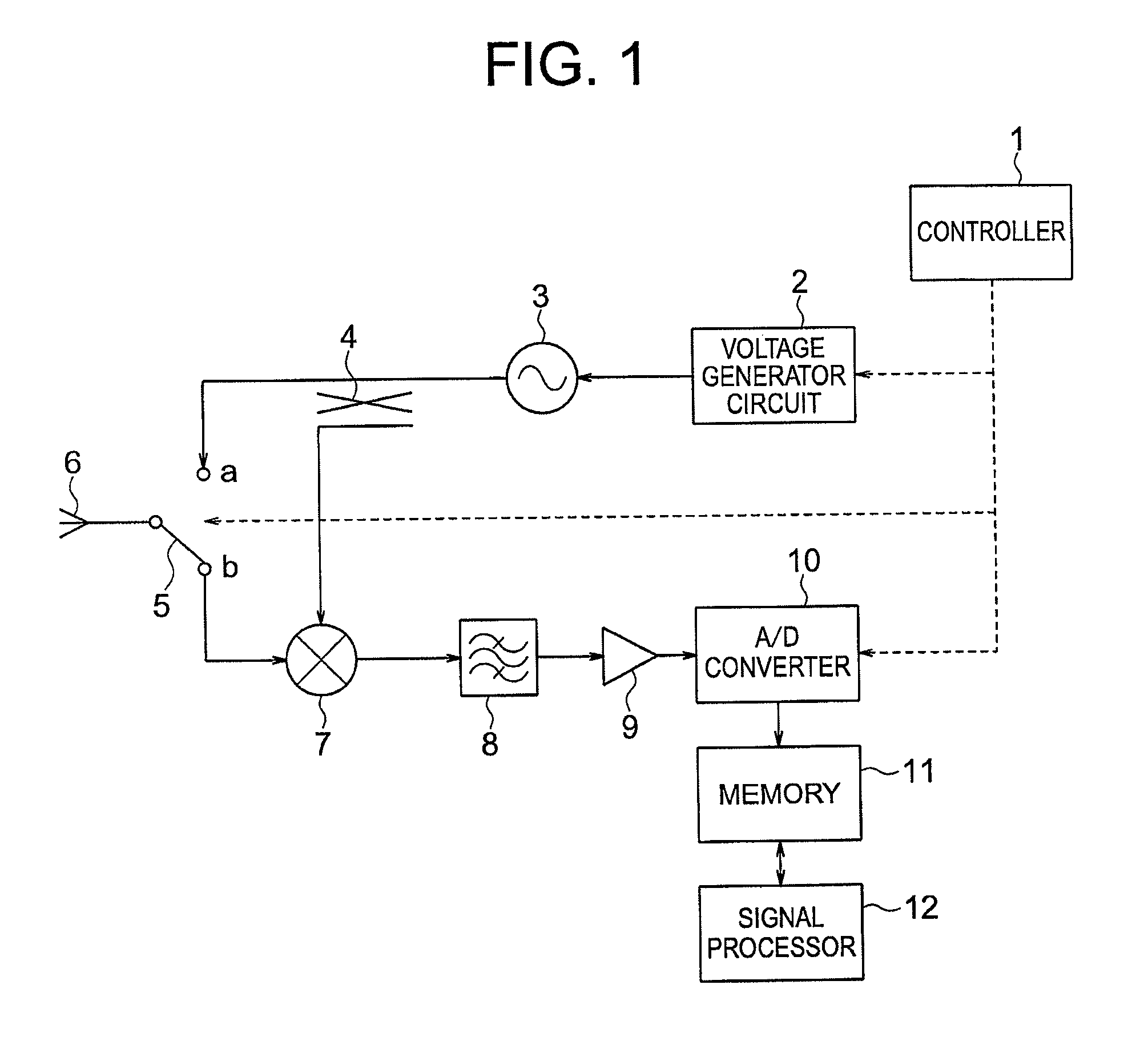
[0052]An on-vehicle radar device according to a first embodiment of the present invention is described with reference to FIGS. 1 to 9B. FIG. 1 is a diagram illustrating the configuration of the on-vehicle radar device according to the first embodiment of the present invention. In the following description, the same reference symbols denote identical or corresponding parts.

[0053]Referring to FIG. 1, the on-vehicle radar device according to the first embodiment of the present invention includes: a controller 1 that controls a voltage generator circuit 1 and the like to be described later; a voltage generator circuit 2 that generates a triangular wave voltage; a voltage controlled oscillator (VCO) 3 that conducts frequency modulation; a distributer 4 that distributes a transmit electric wave; and a switch 5 that changes over between terminals a and b. The on-vehicle radar device also includes: a transmitting and receiving antenna 6; a mixer 7; a bandpass filter 8; an amplifier 9; an an...

second embodiment

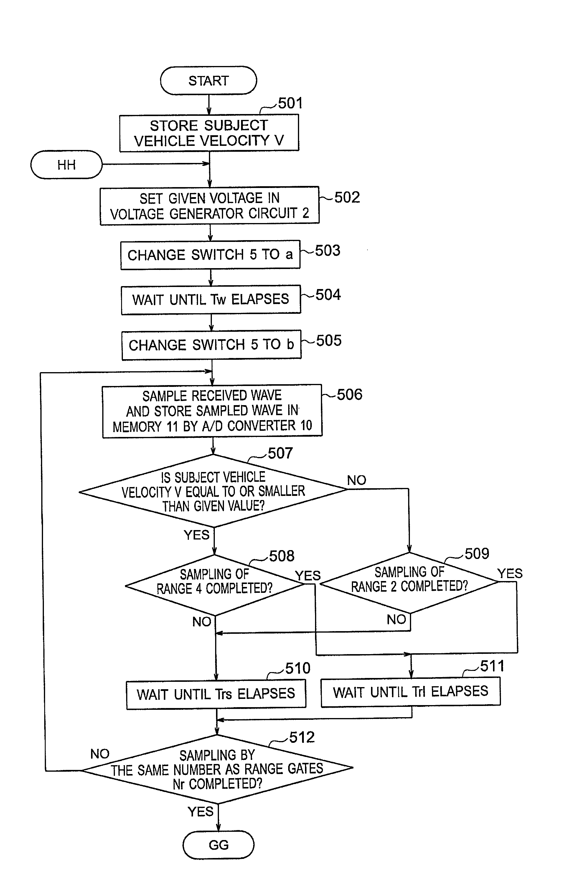
[0124]An on-vehicle radar device according to a second embodiment of the present invention is described. A configuration of the on-vehicle radar device according to the second embodiment of the present invention is similar to that of the above-mentioned first embodiment.

[0125]Only parts different from those in the first embodiment are described. According to the second embodiment, the transmission pulse width and the range gate width are set based on a distance to a leading vehicle.

[0126]According to the second embodiment, the controller 1 controls the switch 5 and the A / D converter 10 according to the distance to the leading vehicle, to thereby change the transmission pulse width and the range gate width. The distance to the leading vehicle is obtained from, for example, the result calculated by the signal processor 12 by Expression (5).

[0127]A method of setting the transmission pulse width and the range gate width based on the distance to the leading vehicle is described in detail...

third embodiment

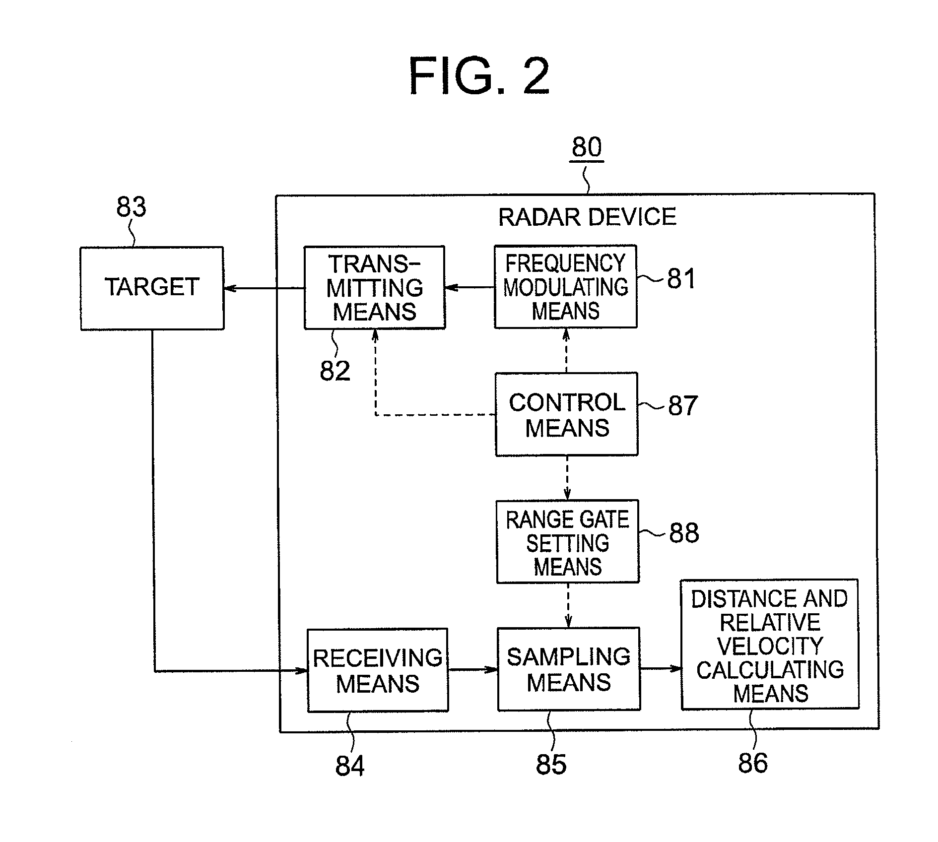
[0133]An on-vehicle radar device according to a third embodiment of the present invention is described with reference to FIGS. 10 to 11B. FIG. 10 is a diagram illustrating a configuration of the on-vehicle radar device according to the third embodiment of the present invention.

[0134]According to the third embodiment, the controller 1 changes the transmission pulse width and the range gate width based on the determination result of open road determining means 13 for determining whether the subject vehicle is traveling on an open road or a free way.

[0135]Only parts different from those in the first embodiment are described. The open road determining means 13 determines whether the subject vehicle is traveling on an open road or a highway, according to the subject vehicle velocity and the distance to the leading vehicle. Specifically, when the distance to the leading vehicle, which has been acquired from the signal processor 12, is equal to or smaller than the distance threshold value,...


PUM


Abstract

A radar device includes: a frequency modulating unit for modulating a frequency of a transmission signal by a triangular wave; a transmitting unit for pulsing the frequency modulated transmission signal to transmit the pulsed transmission signal as a transmission pulse; a receiving unit for generating a beat signal based on a frequency difference between a frequency modulated transmission signal and a reflected received pulse; a range gate setting unit for setting a range gate that determines a sampling timing of the received pulse based on a transmitting timing of the transmission pulse; a sampling unit for sampling the beat signal in each of range gates; a distance and relative velocity calculating unit for calculating a distance to a target and a relative velocity based on the sampled beat signal; and a control unit for controlling a transmission pulse width and a range gate width depending on a subject vehicle velocity.

Description

BACKGROUND OF THE INVENTION[0001]1. Field of the Invention[0002]The present invention relates to a radar device that obtains a distance to a target and a relative velocity, in which a pulse width and a range gate interval (width) are changed depending on a travel environment so as to ensure both of a short-distance precision and a long-distance performance without increasing a calculation amount.[0003]2. Description of the Related Art[0004]Currently known radar devices that are mounted on a vehicle and used for an adaptive cruise control (ACC) or a collision mitigation braking device include a radar device of a frequency modulated continuous wave (FMCW) system (hereinafter, referred to as “FMCW radar device”) which may detect the distance to the target and the relative velocity at the same time. The “FMCW system” is one of radar transmitting systems, and calculates a difference in frequency between a transmission wave and a received wave (a reflected wave resulting from reflecting t...

Claims


Application Information

Patent Timeline
Patent Type & Authority Patents(United States)
IPC IPC(8): G01S13/42G01S13/931
CPCG01S13/18G01S13/345G01S13/931G01S2013/9321G01S2013/9353G01S2013/932
Inventor HAYASE, KEI
Owner MITSUBISHI ELECTRIC CORP
Why Eureka
Try Eureka