Dynamic speed limit system

a speed limit and dynamic technology, applied in the field of information processing systems, can solve the problems of frustrating driving through long construction zones with reduced speed limits, and the speed limit is needlessly enforced for the entire construction zon

Inactive Publication Date: 2009-06-04
IBM CORP
View PDF7 Cites 26 Cited by
  • Summary
  • Abstract
  • Description
  • Claims
  • Application Information

AI Technical Summary

Benefits of technology

[0004]A method, medium and implementing processing system are provided in which the presence of workers in a long highway construction zone is monitored and the electronically-controlled posted speed limit is adjusted in accordance with the detected presence of workers in the immediate area. In an example, Radio Frequency Identification (RFID) scanners or readers are strategically placed in a construction or working area. Such RFID reading devices may be embedded, for example, in construction speed limit signs. The displayed speed limit is controlled by the detected proximity of construction workers wearing RFID-embedded clothing, for example, such as safety vests or helmets. The speed limit sign includes logic to display one of many possible speed limit displays based on the nearest, and / or the number of RFID signals detected in a given area. Vehicular traffic is thereby enabled to travel faster through construction zones where no workers are present and, when appropriate, traffic is slowed when workers are present within a given proximity of the RFID reading devices.

Problems solved by technology

Driving through long construction zones with reduced speed limits is frustrating particularly when no construction workers are in the immediate vicinity.
Typically the workers are isolated on a given part of the highway and yet the speed limit is needlessly enforced for the entire construction zone.

Method used


Image

  • Dynamic speed limit system
  • Dynamic speed limit system
  • Dynamic speed limit system

Examples


Embodiment Construction

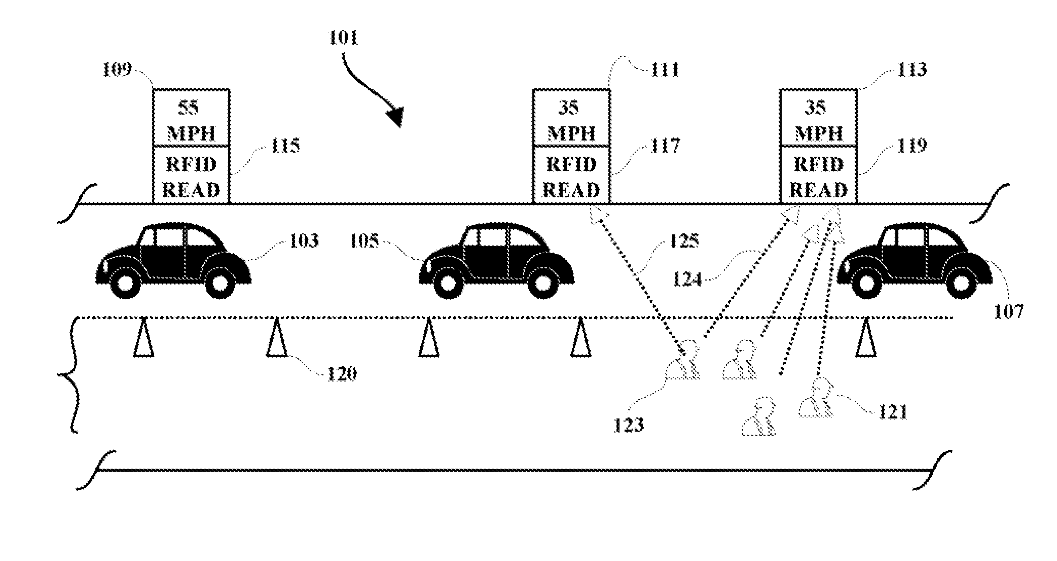
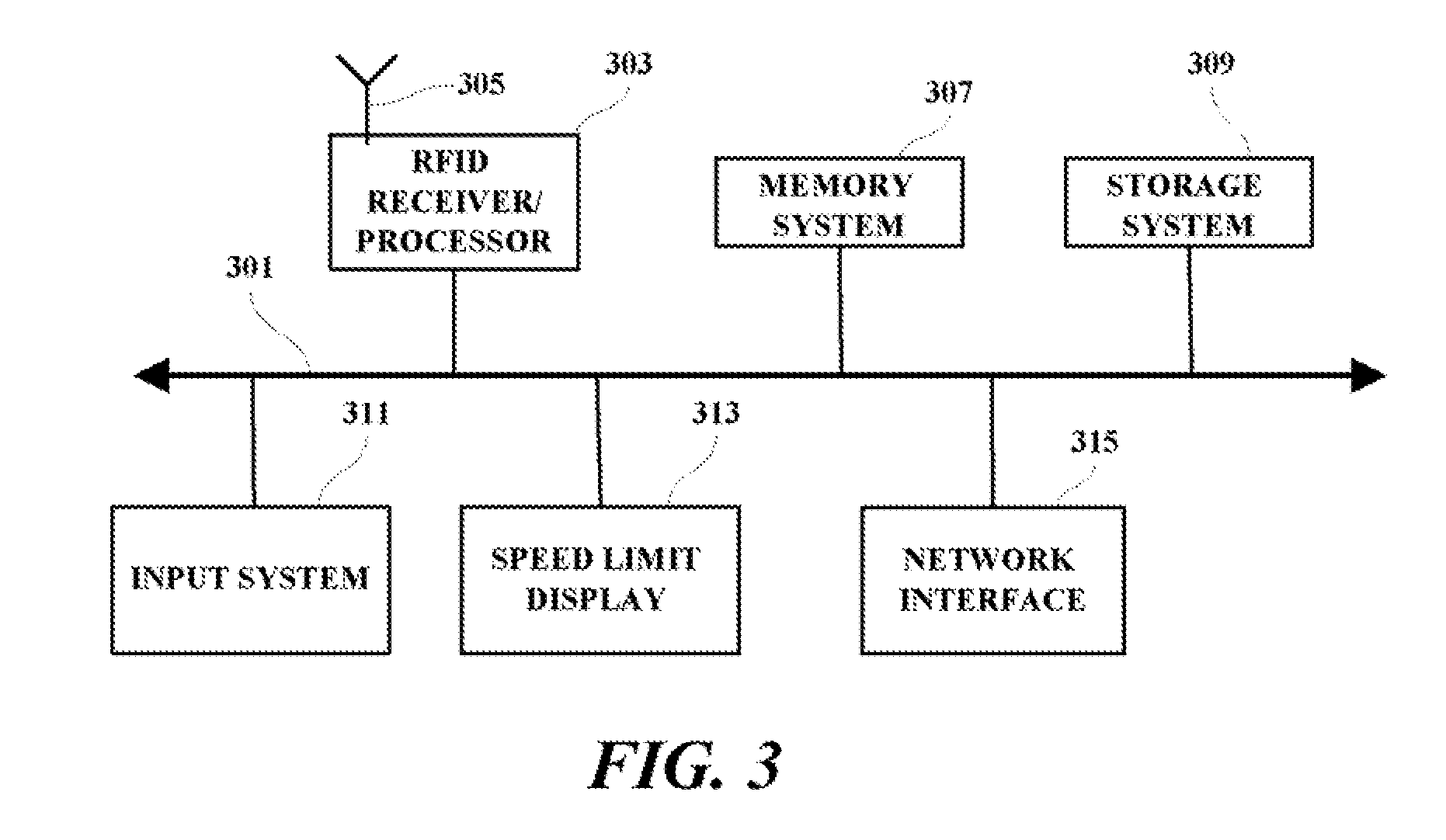
[0011]The various methods discussed herein may be implemented, within a video broadcast system which may include, inter alia, transmission encoding and user de-coding processing systems, a transmission and receiving system, and a user system which may include, inter alia, a user processing device, memory, memory controller and storage and display means. Since the individual components of a transmission and receiving system which may be used to implement the functions used in practicing the present invention are generally known in the art and composed of electronic components and circuits which are also generally known to those skilled in the art, circuit details beyond those shown are not specified to any greater extent than that considered necessary as illustrated, for the understanding and appreciation of the underlying concepts of the present invention and in order not to obfuscate or distract from the teachings of the present invention. Although the invention is illustrated in t...


PUM


Abstract

A method, medium and implementing processing system are provided in which the presence of workers in a long highway construction zone is monitored and the electronically-controlled posted speed limit is adjusted in accordance with the detected presence of workers in the immediate area. In an example, Radio Frequency Identification (RFID) scanners or readers are strategically placed in a construction or working area. Such RFID reading devices may be embedded, for example, in construction speed limit signs. The displayed speed limit is controlled by the detected proximity of construction workers wearing RFID-embedded clothing, for example, such as safety vests or helmets. The speed limit sign includes logic to display one of many possible speed limit displays based on the nearest, and/or the number of RFID signals detected in a given area. Vehicular traffic is thereby enabled to travel faster through construction zones where no workers are present and, when appropriate, traffic is slowed when workers are present within a given proximity of the RFID reading devices.

Description

FIELD OF THE INVENTION[0001]The present invention relates generally to information processing systems and more particularly to a methodology and implementation for adjusting posted speed limits based upon the presence of workers in a predetermined area.BACKGROUND OF THE INVENTION[0002]Driving through long construction zones with reduced speed limits is frustrating particularly when no construction workers are in the immediate vicinity. This type of scenario is particularly true for highway construction where the zones are often miles long. Typically the workers are isolated on a given part of the highway and yet the speed limit is needlessly enforced for the entire construction zone. Construction zones would be less frustrating for travelers if the traveler would be permitted to travel at more appropriate speeds when workers are not present in the immediate area.[0003]Thus there is a need for an improved methodology and implementing system which enables an automatic or dynamic adjus...

Claims


Application Information

Patent Timeline
Patent Type & Authority Applications(United States)
IPC IPC(8): G08G1/01
CPCG08G1/096741
Inventor ARENBURG, ROBERT THOMASBARILLAUD, FRANCKCOBB, BRADFORD LEEDUTTA, SHIVNATH
Owner IBM CORP
Why Eureka
Try Eureka