
Road-rail crane

a technology of road-rail cranes and cranes, which is applied in the direction of cranes, etc., can solve the problems of large blockade of a significant section, considerable economic burden, and inability to reach the end of the train to be rescued

Inactive Publication Date: 2002-01-10
ATECS MANNESMANN AG
View PDF0 Cites 14 Cited by
  • Summary
  • Abstract
  • Description
  • Claims
  • Application Information

AI Technical Summary

Benefits of technology

[0009] A significant difference between the proposed solution and the known machine is that the rail traveling gear no longer has to be carried along with the crane; on the contrary, after the rail crane has been set down onto the road transport means, the crane is transported without the rail traveling gear.
[0010] In accordance with another feature of the invention, the road transport means can be a known towed low-loader, but it can also be one of the special self-powered vehicles which are on the market. The rail traveling gear can be transported on an escort vehicle, as a result of which the transport weight and the transport size of the rail crane are both reduced, and its transportability is considerably improved. The outriggers for the crane used during its operation are mounted so that they can be folded onto the crane undercarriage; attachment means are also provided on the crane undercarriage, to which the rail bogies can be quickly adapted.
[0012] In accordance with another feature of the invention, the crane is designed so that the contours of the rail crane, including the folded-in outriggers, remain within the allowable structure clearance for rail travel and within the allowable road transport dimensions for road travel. This feature permits the rail crane to travel quickly over the road without being subject to the traffic restrictions applicable to special travel by extra-wide vehicles; in addition, the rail crane can travel over the rails to the work site without the need to make modifications to it to achieve the prescribed structure clearance.
[0014] The particular advantage of the rail crane according to the invention is that it can be set up very quickly and precisely by the use of the process according to the invention, which is characterized by the following work steps:
[0024] The ability to position the crane precisely can be improved if desired by providing the bases of the crane outrigger system with integrated devices for sliding the support cylinders crosswise to the outrigger bases.
[0025] The particular advantage of the present invention can be described in summary as follows: the rail crane, which is ready for duty except for its rail traveling gear, can be transported on a standard commercial road low- loader or by means of its own bolted-on road traveling gear in either a transverse or longitudinal orientation to the desired section of track until its center of rotation is centered over the tracks. After the outriggers have been flipped out, the rail crane is raised by the support cylinders until the low-loader can be driven out from underneath the crane or until the bolted-on road traveling gear can be disconnected from the undercarriage. Then the rail traveling gear, which has preferably been transported separately, is lifted by the crane's own hook from the accompanying truck and swung over to the quick adapters of the undercarriage and attached there. As a result, the shortest possible setup time is achieved. The transport weight and transport dimensions allow rapid and easy transport of even large rail cranes to the work site.

Problems solved by technology

This was a disadvantage in cases where, for example, rescue operations were to be performed on sections of track where an accident had occurred, but the end of the train to be rescued could not be reached because the rails were blocked.
This meant the blocking of a significant section of track, the loss of much time, and considerable economic burden.
The track-bound rail crane cannot 15 be broken down into parts and is too heavy to be transported by road vehicles.
As a result, the shortest possible setup time is achieved.

Method used


Image

  • Road-rail crane
  • Road-rail crane
  • Road-rail crane

Examples


Embodiment Construction

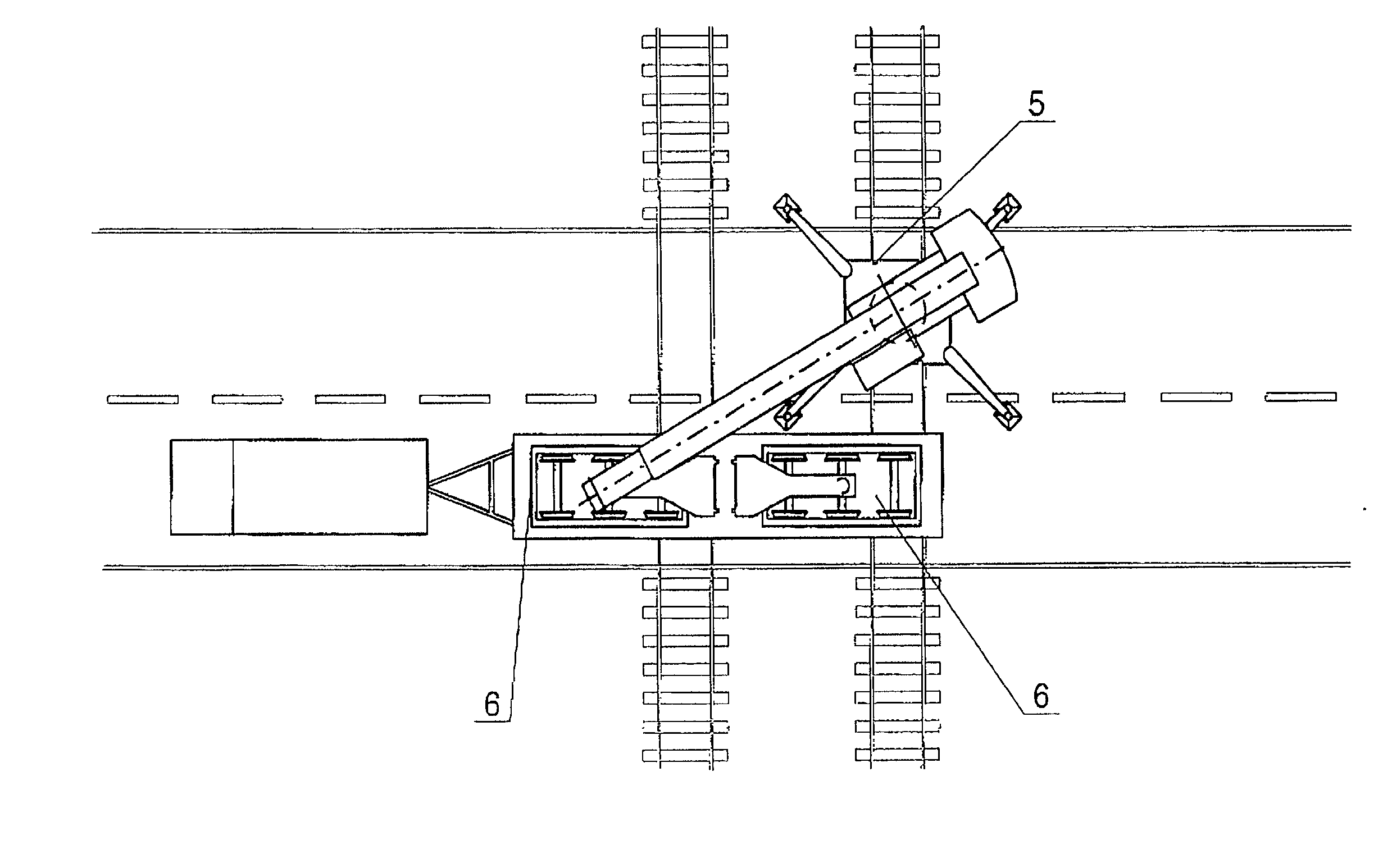
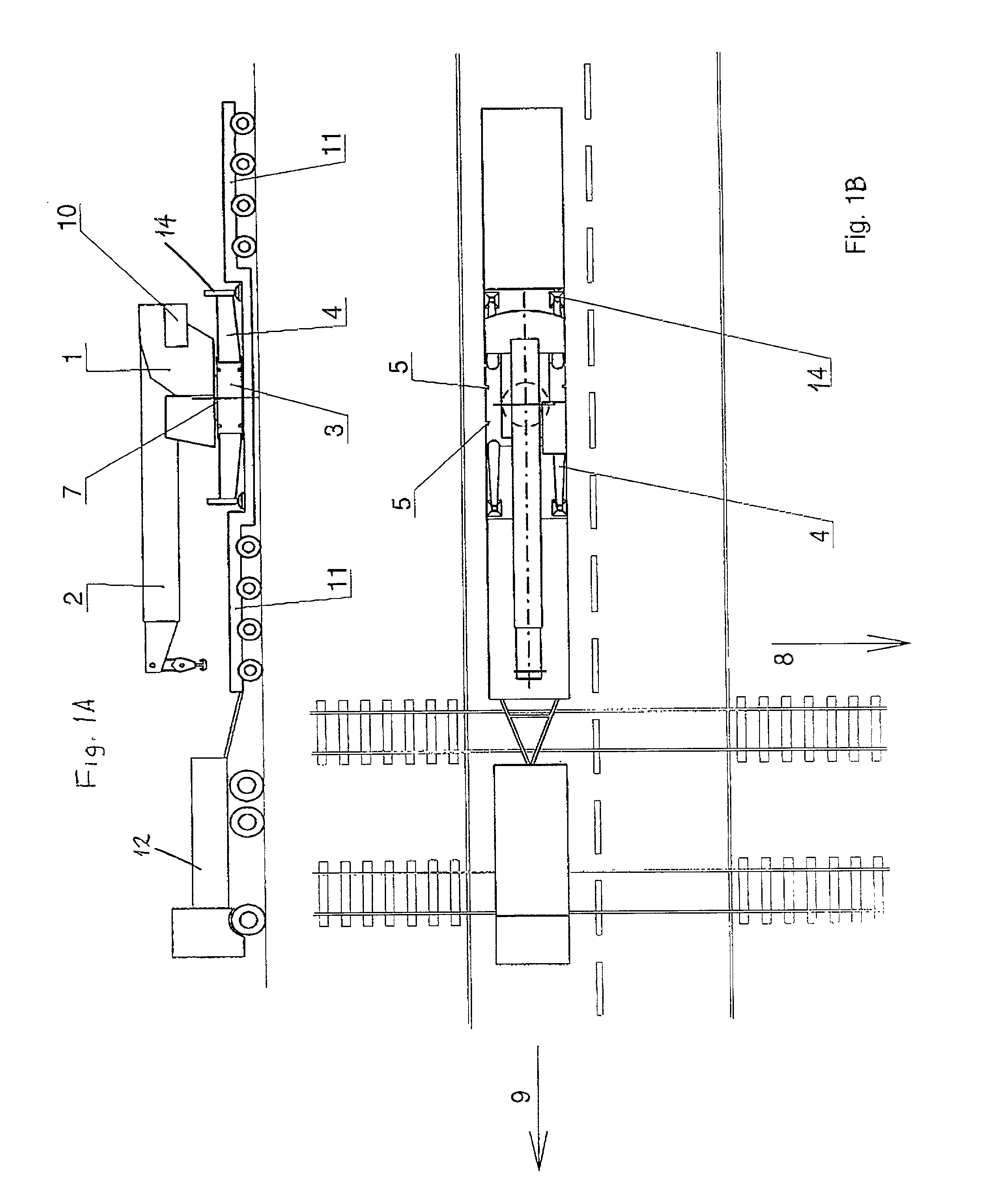
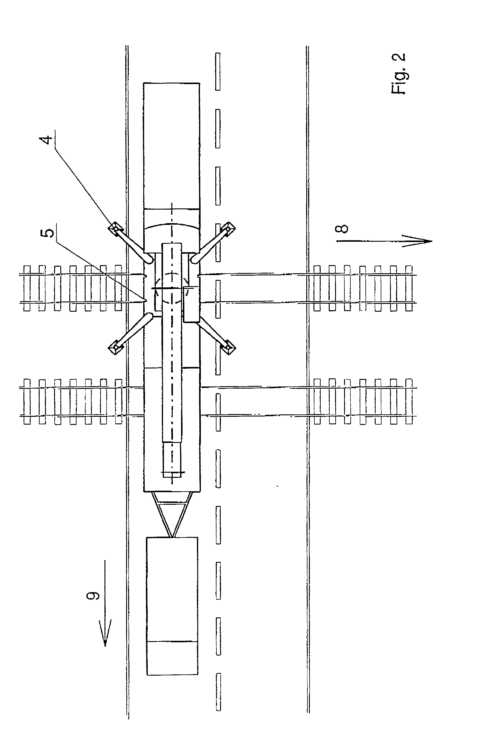
[0032] The rail crane according to FIG. 1 consists of the crane superstructure 1 with the telescoping boom 2 and the crane undercarriage 3. The folding outriggers 4 are hinged to the crane undercarriage 3; quick adapters 5 are also provided on the undercarriage, to which the rail traveling gears 6 to be described later are attached. The superstructure and the undercarriage of the crane are connected to each other by a rotary joint 7 in such a way that the upper carriage can rotate without restriction. The undercarriage 3 is designed so that it can be transported over the road 9. For this purpose, the outriggers 4 can be folded in so that they point in the travel direction and do not project beyond the contours of the road transport A) vehicle 11. In the example shown, the crane counterweight 10 remains on the superstructure 2 while the crane is traveling over the road; if weight is a problem, the counterweight can also be transported by a separate vehicle.

[0033] The individual phase...


PUM


Abstract

A road-rail crane includes a crane undercarriage with spreadable outriggers hinged to the undercarriage; a crane superstructure connected to the crane undercarriage with freedom of rotation, the luffing boom of the crane being mounted on the superstructure; and rail traveling gear attached to the crane undercarriage for rail travel. The crane undercarriage and the crane superstructure can be carried temporarily as a single transportable unit by a road transport means, which can be removed and then replaced by the rail traveling gear, which can be connected to the crane undercarriage, after the crane undercarriage has been supported and raised on the spread-out outriggers.

Description

[0001] 1. Field of the Invention[0002] The invention pertains to a road-rail crane, consisting of a crane undercarriage mounted on road transport gear; spreadable outriggers hinged to the crane undercarriage; a crane superstructure, which is connected to the crane undercarriage with freedom to rotate, the luffing boom of the crane being mounted on the superstructure; and rail traveling gear attached to the crane undercarriage for traveling on the rails.[0003] 2. Description of the Related Art[0004] to So-called road-rail vehicles for combination use on the road and on rails are known. The advantage of these machines is that the vehicle can start out on the road and then be put on the tracks in a relatively short time to move loads over the rails. A typical unit of this type is illustrated and described in the prospectus entitled "Demag Telescoping Crane AC 50R, On Road and Rail". The known machine can be used either as a rail crane or as a telescoping road crane for the rescue of bo...

Claims


Application Information

Patent Timeline
IPC IPC(8): B66C23/38B66C23/36B66C23/50
CPCB66C23/38B66C23/50
Inventor RODE, RALFSPRAVE, KLAUS
Owner ATECS MANNESMANN AG
Learn More