Image display apparatus and image display method

a technology of image display and image, applied in the direction of instruments, computing, electric digital data processing, etc., can solve the problems of uneven luminance between dark background regions, difficult to remove unevenness, and inability to make the optical transmittance of liquid crystal small enough to display the dark background, etc., to achieve the effect of suppressing luminance unevenness

Active Publication Date: 2009-06-04
HISENSE VISUAL TECH CO LTD
View PDF16 Cites 52 Cited by
  • Summary
  • Abstract
  • Description
  • Claims
  • Application Information

AI Technical Summary

Problems solved by technology

This is caused by the fact that it is in principle impossible to make the optical transmittance of liquid crystal small enough to display the dark background.
If a region expressing a bright source in a dark background and a region expressing only a dark background are adjacent to each other, the brightness of the displayed background differs between these regions and consequently unevenness occurs between the dark background regions.
However, since there is a limit in the black display capability of the liquid crystal as described above, it is difficult to remove this unevenness by only correction of the transmittance when the back light luminance difference between the adjacent regions is large.
In principle, it is impossible to compensate the luminance difference between the two regions.
Therefore, unevenness occurs between the two regions.

Method used


Image

  • Image display apparatus and image display method
  • Image display apparatus and image display method
  • Image display apparatus and image display method

Examples


first embodiment

[0029]An image display apparatus according to a first embodiment of the present invention will now be described with reference to FIGS. 1 to 12(b).

[0030](1) Configuration of Image Display Apparatus

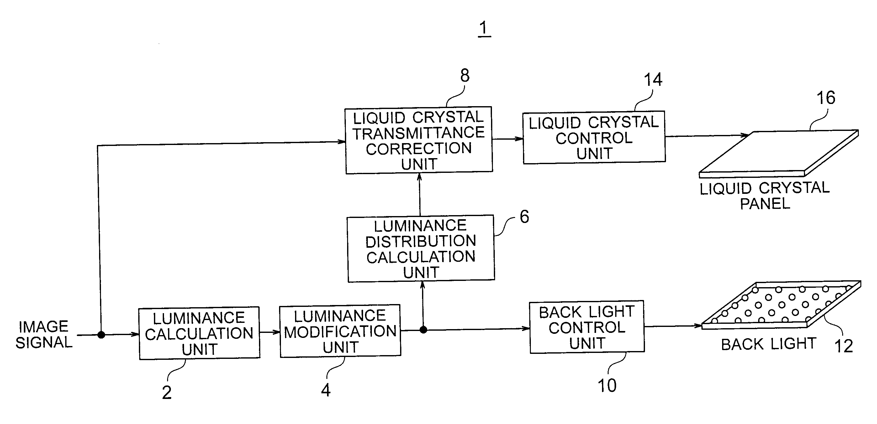
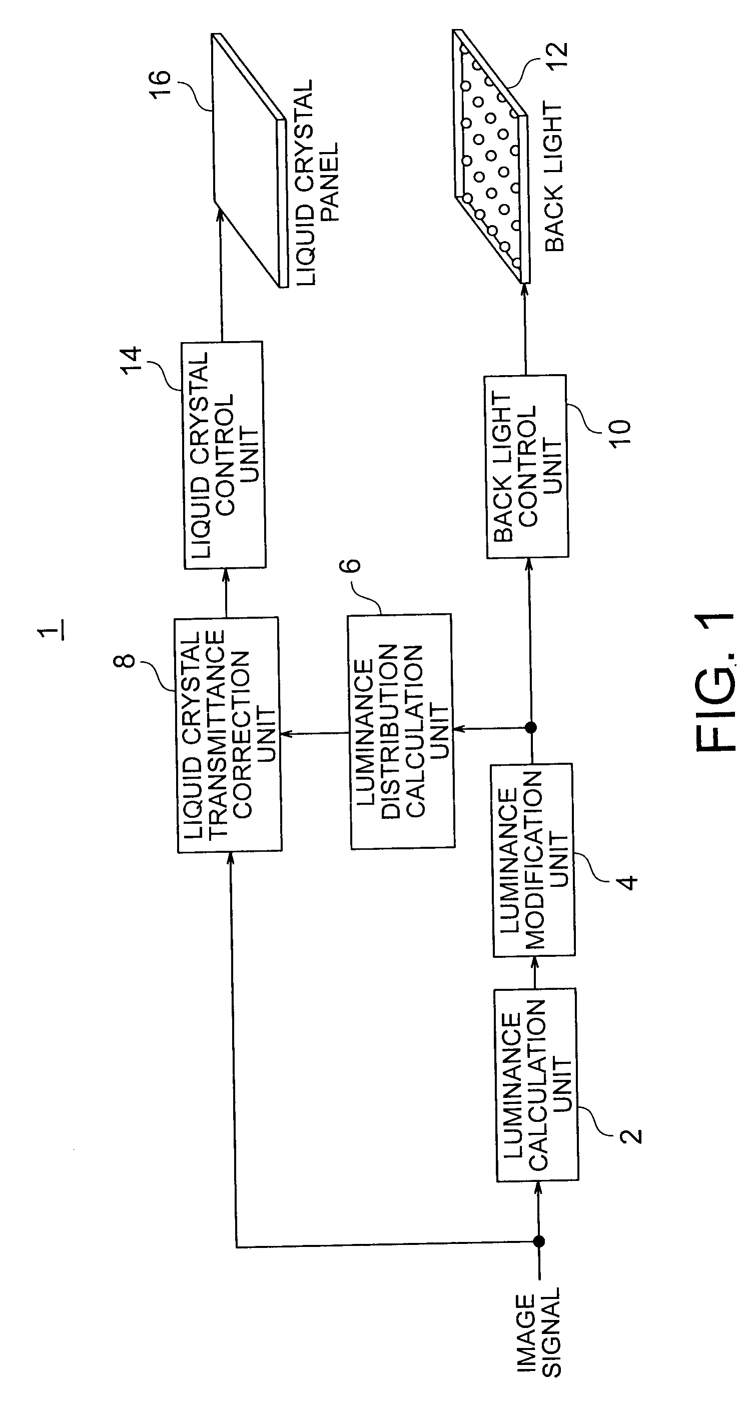
[0031]A configuration of an image display apparatus according to the present embodiment is shown in FIG. 1. The image display apparatus 1 according to the present embodiment includes a luminance calculation unit 2, a luminance modification unit 4, a luminance distribution calculation unit 6, a transmittance correction unit 8, a back light control unit 10, a back light 12, a liquid crystal control unit 14, and a liquid crystal panel 16 having a plurality of pixels arranged in a matrix form.

[0032]The luminance calculation unit 2 calculates a luminance setting value of the back light 12 suitable for display on the basis of an image signal. The luminance modification unit 4 modifies the setting value calculated by the luminance calculation unit 2. The luminance distribution calculation unit 6 ...

second embodiment

[0078]An image display apparatus according to a second embodiment will now be described.

[0079]Although the image display apparatus according to the present embodiment is the same in basic configuration as the image display apparatus according to the first embodiment shown in FIG. 1, the image display apparatus according to the present embodiment is different from the display apparatus according to the first embodiment in the configuration of the luminance modification unit 4.

[0080]Luminance Modification Unit

[0081]The luminance modification unit 4 according to the second embodiment calculates a difference value between a luminance setting value of back light 12 of a pertinent partial region and a luminance setting value of the back light 12 in a partial region neighboring the pertinent partial region, calculates a weight so as to make a weight for a neighboring partial region larger as the difference value for the neighboring partial region is greater, calculates a weighted average o...

third embodiment

[0094]An image display apparatus according to a third embodiment will now be described. Although the image display apparatus according to the present embodiment is the same in basic configuration as the image display apparatus according to the first embodiment, the image display apparatus according to the present embodiment is different from the display apparatus according to the first embodiment in the configuration of the luminance modification unit 4.

[0095]Luminance Modification Unit

[0096]The luminance modification unit 4 according to the present embodiment calculates the luminance setting value in the pertinent partial region so that a luminance gradient in a partial region neighboring the pertinent partial region which is an object of modification of luminance setting value becomes equal to a threshold or less. Operation of the luminance modification unit 4 will now be described with reference to FIGS. 17(a) and 17(b).

[0097]First, from among partial regions neighboring the pert...


PUM


Abstract

An image display apparatus includes: a luminance modification unit configured to modify the luminance setting value so as to make a luminance difference between adjacent partial regions of a back light smaller; a luminance distribution calculation unit configured to calculate a predicted value of luminance distribution of light incident on a liquid crystal panel from the back light on the basis of the modified luminance setting value; a liquid crystal transmittance correction unit configured to correct an optical transmittance of the image signal at each pixel of the liquid crystal panel on the basis of the image signal and the luminance distribution; a back light control unit configured to control the back light on the basis of the modified luminance setting value; and a liquid crystal control unit configured to control the liquid crystal panel so that the transmittance of the image signal becomes the corrected optical transmittance.

Description

CROSS-REFERENCE TO RELATED APPLICATION[0001]This application is based upon and claims the benefit of priority from prior Japanese Patent Application No. 2007-313485 filed on Dec. 4, 2007 in Japan, the entire contents of which are incorporated herein by reference.BACKGROUND OF THE INVENTION[0002]1. Field of the Invention[0003]The present invention relates to an image display apparatus and an image display method.[0004]2. Related Art[0005]In the conventional liquid crystal display apparatus, back light luminance control is conducted by dividing the screen into a plurality of regions with the object of expanding the display dynamic range and reducing the power dissipation. For example, according to JP-A 2005-258403 (KOKAI), back light luminance is controlled so as to make the back light luminance in each of regions obtained by division equal to at least the maximum display luminance of a video signal in the region.[0006]When it is attempted to display an image expressing a light source...

Claims


Application Information

Patent Timeline
Patent Type & Authority Applications(United States)
IPC IPC(8): G09G3/36
CPCG09G3/3426G09G2320/0233G09G2360/16G09G2320/0646G09G2330/021G09G2320/064
Inventor NONAKA, RYOSUKEBABA, MASAHIROITOH, GOH
Owner HISENSE VISUAL TECH CO LTD
Why Eureka
Try Eureka