Projection image display position control device, projection image display position control method, and projection system

a projection image and control device technology, applied in the direction of projectors, optics, instruments, etc., can solve the problems of difficult to accurately display projection images, deteriorating image quality, and image moiré, so as to reduce the movable range of the display position control mechanism

Active Publication Date: 2009-06-04
SEIKO EPSON CORP
View PDF9 Cites 11 Cited by
  • Summary
  • Abstract
  • Description
  • Claims
  • Application Information

AI Technical Summary

Benefits of technology

[0020]It is an advantage of some aspects of the invention to provide a projection image display position control device, a projection image display position control method, and a projection system capable of reducing a movable range of a display position control mechanism and achieving appropriate position control.
[0022]According to the display position control device for projection image having this structure, the projection image can be accurately displayed at the display target position at the time of projection of the projection image at the predetermined position on the projection screen. In this step, the display position control processing unit performs display position control an integer number times larger than the pixel pitch. Thus, pixels are shifted by the unit of pixels, and display position control is easily performed without deterioration of image quality. Also, the display position control mechanism performs display position control smaller than the pixel pitch. Thus, the movable range of the display position control mechanism is extremely decreased, and the projector can be made compact.
[0024]According to this structure, the display position control processing unit performs display position control by shifting pixels by a value an integer number times larger than the pixel pitch. Thus, display position control can be easily executed without deterioration of image quality.
[0026]According to this structure, the optical display position control is performed by displacing the optical axis of the projection image by the value smaller than the pixel pitch. Thus, the movable range of the display position control mechanism can be decreased, and the projector can be made compact.
[0030]Moreover, the display position control device for projection image performs display position control for the projection images other than the reference projection image. Thus, display position control can be more efficiently performed than display position control performed for all of plural projection images. Furthermore, the display position control units such as the display position adjustment control unit, the display position control processing unit, and the display position control mechanism are provided only on the projector for performing display position control. Thus, the entire structure of the projection system can be simplified.
[0034]According to this display position control method for projection image, advantages similar to those of the display position control device for projection image according to the first aspect of the invention can be provided. It is preferable that the advantages similar to those of the display position control device for projection image according to the first aspect of the invention can be provided.

Problems solved by technology

In case of the stack projection described above, however, it is not easy to accurately display the projection images from the two projectors at target display positions (display target positions) specified for each of the projection image on the screen.
When the projection images from the plural projectors are not displayed at the display target positions, the image quality of the projection image deteriorates.
In this case, there is also a possibility that noise such as moiré is caused on the image which is originally free from such noise.
However, there is a possibility of deterioration of image quality caused by image processing.
In this case, image quality deteriorates.

Method used


Image

  • Projection image display position control device, projection image display position control method, and projection system
  • Projection image display position control device, projection image display position control method, and projection system
  • Projection image display position control device, projection image display position control method, and projection system

Examples


first embodiment

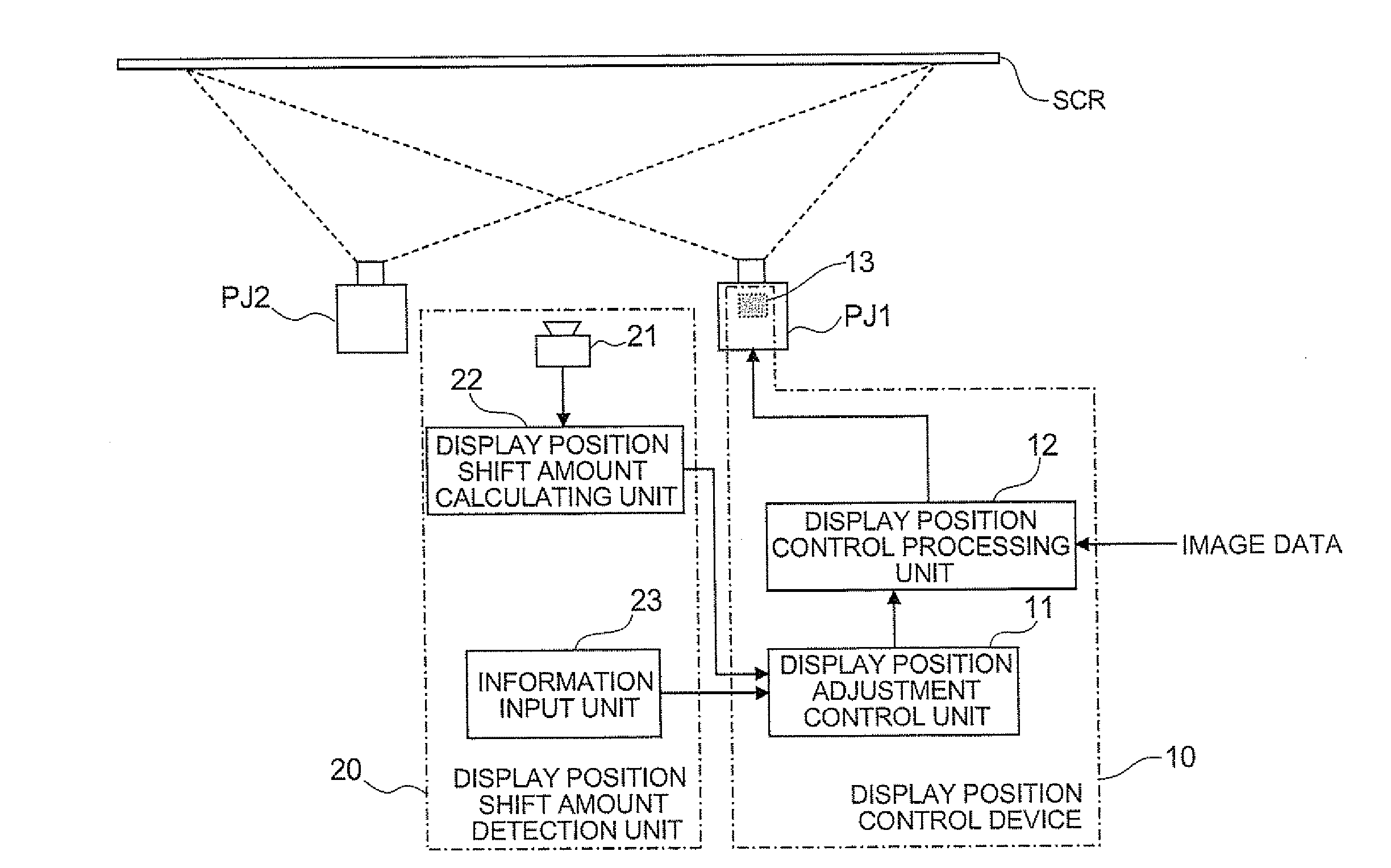
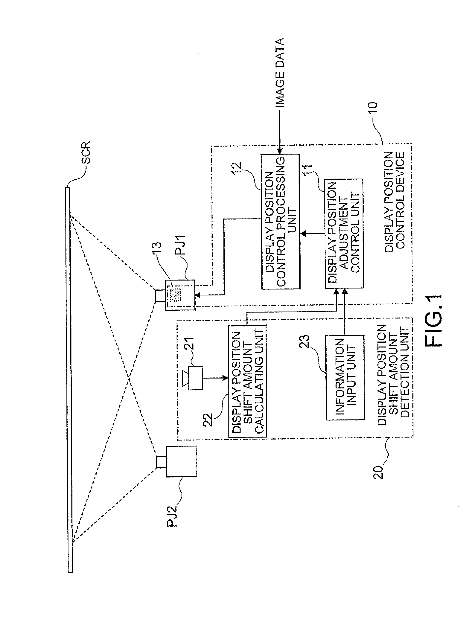
[0047]FIG. 1 illustrates a structure of a projection system according to a first embodiment. As illustrated in FIG. 1, the projection system in the first embodiment includes two projectors PJ1 and PJ2, and a display position control device 10 and a display position shift amount detection unit 20 for detecting display position shift amount provided one of the two projectors PJ1 and PJ2. According to the projection system shown in FIG. 1, the display position control device 10 is disposed on the projector PJ1 side.

[0048]In the projection system according to the first embodiment, the two projectors PJ1 and PJ2 are so designed as to perform so-called stacking projection which overlaps respective projection images projected from the two projectors PJ1 and PJ2 on a screen SCR as a projection surface.

[0049]Examples of this stacking projection involve a projection method for performing high-luminance image display by completely matching corresponding pixels on the projection images projecte...

second embodiment

[0076]In the first embodiment, display position control by stacking respective projection images from the two projectors on the screen SCR has been discussed. In the second embodiment, display position control of one projection image projected from one projector is explained.

[0077]FIG. 3 illustrates a structure of a projection system according to the second embodiment. As illustrated in FIG. 3, the projection system in the second embodiment includes one projector (projector PJ1 in this example), the display position control device 10, and the display position shift amount detection unit 20. The display position control device 10 has the display position adjustment control unit 11, the display position control processing unit 12, and the display position control mechanism 13 similarly to the projection system in the first embodiment (see FIG. 1). The display position shift amount detection unit 20 also has the image pickup device 21 such as a camera, the display position shift amount...


PUM


Abstract

A display position control device for projection image which controls a display position of a projection image displayed on a projection surface includes: a display position adjustment control unit which divides display position shift amount from a display target position of the projection image on the projection surface into a value an integer number times larger than a pixel pitch of the projection image and a value smaller than the pixel pitch; a display position control processing unit which performs display position control through image processing based on the value the integer number times larger than the pixel pitch; and a display position control mechanism which performs optical display position control based on the value smaller than the pixel pitch.

Description

[0001]This application claims priority from Japanese Patent Application No. 2007-310009 filed in the Japanese Patent Office on Nov. 30, 2007, the entire disclosure of which is hereby incorporated by reference in its entirety.BACKGROUND[0002]1. Technical Field[0003]The present invention relates to a projection image display position control device, a projection image display position control method, and a projection system.[0004]2. Related Art[0005]A method for performing stack projection of identical images on one screen (projection surface) by using a plurality of projectors is known. When pixels on the projection image from one of the plural (two in this case) projectors are matched with the corresponding pixels on the projection image from the other projector in the stack projection, the luminance of the projection images on the screen is substantially doubled, and thus high-luminance image display can be achieved. Moreover, when the corresponding pixels are shifted by ½ pixel in...

Claims


Application Information

Patent Timeline
Patent Type & Authority Applications(United States)
IPC IPC(8): G03B21/00
CPCG03B21/00G03B21/005
Inventor YOSHIZAWA, KOICHI
Owner SEIKO EPSON CORP
Why Eureka
Try Eureka