
LED lamp

Inactive Publication Date: 2009-06-04
FU ZHUN PRECISION IND SHENZHEN +1
View PDF2 Cites 58 Cited by
  • Summary
  • Abstract
  • Description
  • Claims
  • Application Information

AI Technical Summary

Benefits of technology

[0005]A conventional LED lamp comprises a heat sink and a plurality of LED modules having LEDs attached to an outer surface of a heat sink to dissipate heat generated by the LEDs. The outer surface of the heat sink generally is a plane and the LEDs are arranged close to each other. When the LED lamp works, the LEDs mounted on the planar outer surface of the heat sink only form a flat light source. However, once the LED lamp is fixed under a determined circumstance, a direction of a light emitted by the LED lamp cannot be changed to meet different requirements. Generally, when it is necessary to change the illumination direction, the LED lamp must be remounted or redesigned, which is unduly time-consuming and raises production costs.

Problems solved by technology

However, once the LED lamp is fixed under a determined circumstance, a direction of a light emitted by the LED lamp cannot be changed to meet different requirements.
Generally, when it is necessary to change the illumination direction, the LED lamp must be remounted or redesigned, which is unduly time-consuming and raises production costs.

Method used


Image

  • LED lamp
  • LED lamp
  • LED lamp

Examples


Embodiment Construction

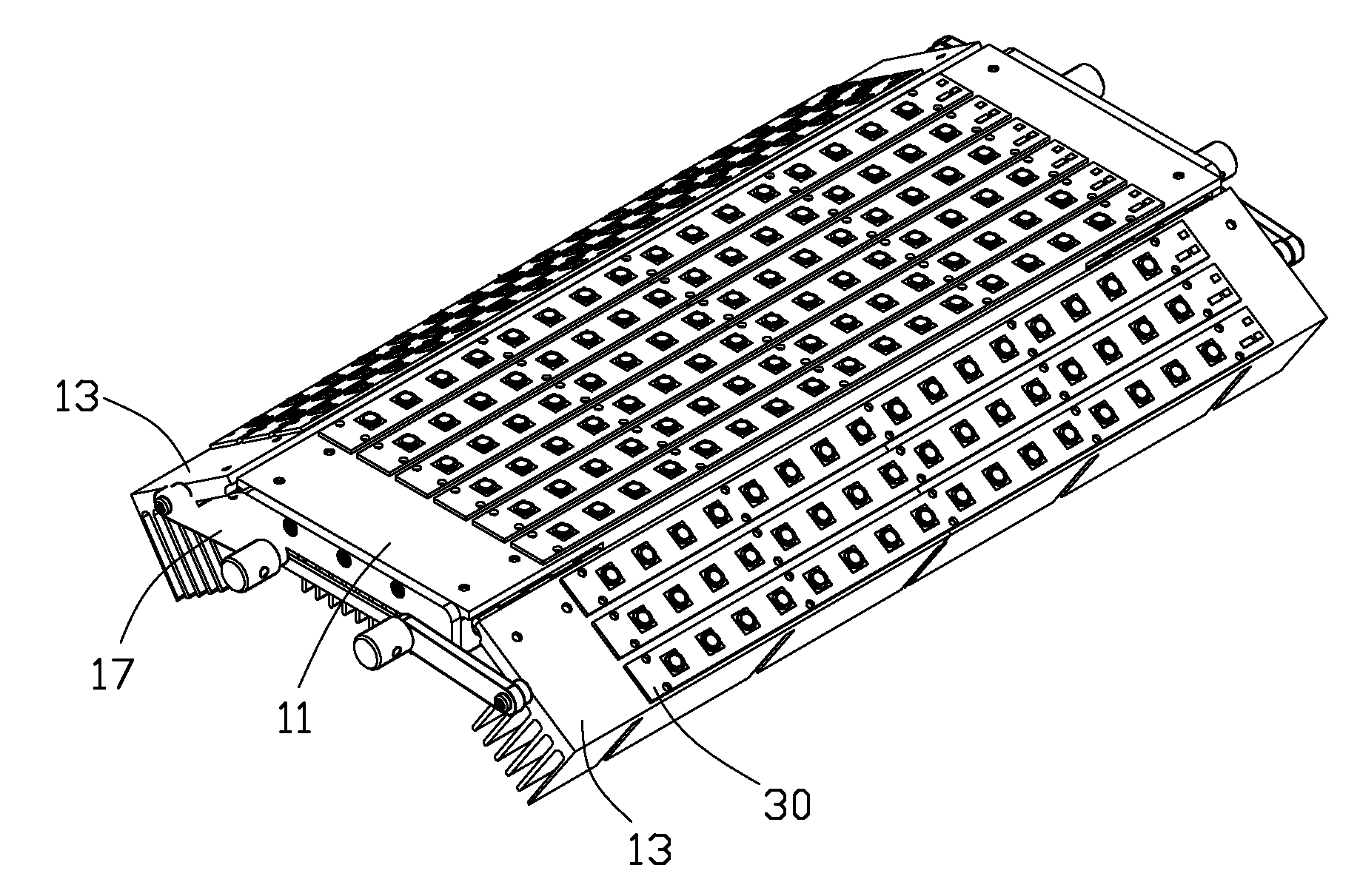
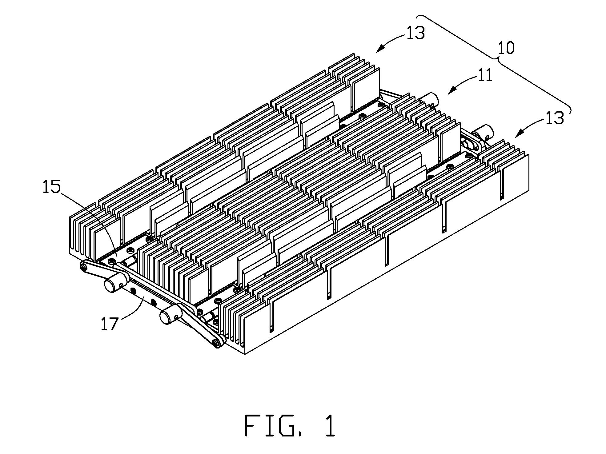
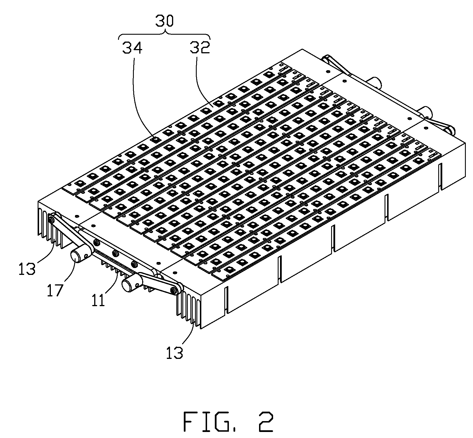
[0016]Referring to FIGS. 1-2, an LED lamp in accordance with a preferred embodiment of the present invention comprises a heat dissipation device 10, an adjustable device (not labeled) mounted on the heat dissipation device 10 for varying a direction of illumination of the LED lamp and a plurality of LED modules 30 mounted on the heat dissipation device 10. The heat dissipation device 10 is used to cool down the LED modules 30 to keep them working within an acceptable temperature range.

[0017]Referring to FIGS. 3-4, the heat dissipation device 10 comprises a first heat sink 11, and two second heat sinks 13 located at opposite sides of the first heat sink 11. The first and second heat sinks 11, 13 each are integrally formed by aluminum extrusion. Two pairs of metal hinges 15 are located between the first heat sink 11 and the second heat sinks 13 to hinge the first and second heat sinks 11, 13 together for achieving pivotal movement of the second heat sinks 13 relative to the first heat...


PUM


Abstract

An LED lamp includes a first heat sink, a second heat sink and a plurality of LED modules. The second heat sink is located at a lateral side of the first heat sink and pivotally connects with the first heat sink. The LED modules are evenly attached on bottoms of the first and second heat sinks. The second heat sink can be rotated relative to the first heat sink to be fixed at a required position, whereby an illumination angle of the LED lamp can be adjusted. Heat generated by the LED modules is dissipated by the first and second heat sinks.

Description

BACKGROUND OF THE INVENTION[0001]1. Field of the Invention[0002]The present invention relates to an LED lamp, and more particularly to an LED lamp having an adjustable device for adjusting the LED lamp to assume various angles of illumination. Furthermore, the LED lamp has a heat dissipation device for dissipating heat generated by the LED lamp.[0003]2. Description of Related Art[0004]The technology of light emitting diodes has rapidly developed in recent years from indicators to illumination applications. With the features of long-term reliability, environment friendliness and low power consumption, the LED is viewed as a promising alternative for future lighting products.[0005]A conventional LED lamp comprises a heat sink and a plurality of LED modules having LEDs attached to an outer surface of a heat sink to dissipate heat generated by the LEDs. The outer surface of the heat sink generally is a plane and the LEDs are arranged close to each other. When the LED lamp works, the LED...

Claims


Application Information

Patent Timeline
IPC IPC(8): F21V17/02F21V21/00F21V29/00
CPCF21K9/00F21V29/73F21V29/763F21V29/77F21V29/2212F21V19/02F21Y2101/02F21Y2103/003F21Y2105/001F21K9/58F21V14/02F21Y2105/10F21K9/65F21Y2103/10F21Y2115/10F21V29/75F21V29/74
Inventor ZHANG, WEN-XIANGYU, GUANGFENG, JIN-SONGZHOU, ZHI-YONG
Owner FU ZHUN PRECISION IND SHENZHEN
Learn More