Optical information recording medium

a technology of optical information and recording medium, which is applied in the field can solve the problems of low sensitivity of optical beam and slow recording speed of optical information recording medium, and achieve the effects of increasing recording speed, reducing recording time required to form recording marks on activated recording areas, and reducing recording tim

Inactive Publication Date: 2009-06-04
SONY CORP
View PDF18 Cites 1 Cited by
  • Summary
  • Abstract
  • Description
  • Claims
  • Application Information

AI Technical Summary

Benefits of technology

[0013]Accordingly, the recording time required to form the recording mark on the activated recording area can be reduced, compared with that of the non-recording area.
[0014]According to an embodiment of the present invention, the recording time required to form the recording mark on the activated recording area can be reduced. Thus, an optical information recording medium that can increase the recording speed can be realized.
[0015]Moreover, according to an embodiment of the present invention, the recording time required to form the recording mark on the activated recording area can be reduced, compared with that of the non-recording area. Thus, an optical information recording medium that can increase the recording speed can be realized.

Problems solved by technology

However, there are some problems: such an optical information recording medium has a low sensitivity to an optical beam.
Moreover, in order to form a recording mark, the optical information recording medium needs to be exposed to an optical beam for a relatively long time, and the recording speed is not fast.

Method used


Image

  • Optical information recording medium
  • Optical information recording medium
  • Optical information recording medium

Examples


first embodiment

(1) First Embodiment

(1-1) CONFIGURATION OF OPTICAL INFORMATION RECODING MEDIUM

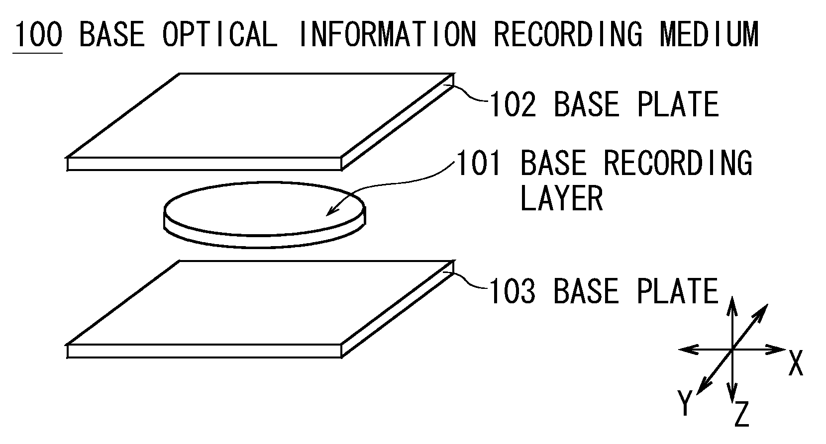
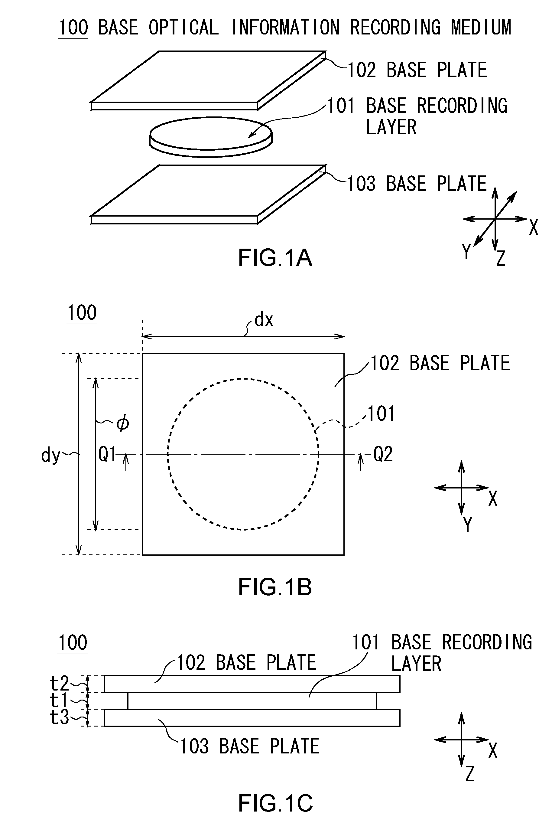
[0037]As shown in FIGS. 1A to 1C, a base optical information recording medium 100 includes a base plate 102 and a base plate 103. Between the base plates 102 and 103, a base recording layer 101 is formed. Accordingly, the base optical information recording medium 100, as a whole, works as a medium on which information is recorded.

[0038]The base plates 102 and 103 are glass substrates. The base plates 102 and 103 have high light transmittance. The base plates 102 and 103 are square or rectangular in shape: the lengths dx and dy of the base plates 102 and 103 in X and Y directions are about 50 mm while the thickness t2 and the thickness t3 are about 0.6 to 1.1 mm.

[0039]AntiReflection coating (AR) is applied to the outer surfaces of the base plates 102 and 103 (those surfaces does not touch the base recording layer 101) by four-layer anorganic substances (Nb2O2 / SiO2 / Nb2O5 / SiO2) that do not reflect an optical...

second embodiment

(2) Second Embodiment

(2-1) FORMATION OF ACTIVATED RECORDING AREA

[0177]FIGS. 9 to 13 illustrate a second embodiment, and the parts of FIGS. 9 and 13 have been designated by the same symbols as the corresponding parts of FIGS. 1 to 8 illustrating the first embodiment. The second embodiment differs from the first embodiment: in the second embodiment, as the second initialization beam FL2, a second initialization beam FL2y converged by a cylindrical lens is emitted to the base recording layer 101 in a layer patter, whereas in the first embodiment, it is emitted to the whole area of the base recording layer 101. Incidentally, the configuration of the second-embodiment base optical information recording medium 100 and optical information recording and reproducing device 5 is the same as that of the first embodiment, and their description will be omitted.

[0178]As shown in FIG. 9, a second initialization device 30 emits the second initialization beam FL2y whose wavelength is 406 nm from a l...

third embodiment

(3) Third Embodiment

(3-1) PRODUCTION OF RE-INITIALIZATION OPTICAL INFORMATION RECORDING MEDIUM

[0208]FIGS. 15 to 18 illustrate a third embodiment. The parts of FIGS. 15 to 18 have been designated by the same symbols as the corresponding parts of FIGS. 9 to 14. The third embodiment differs from the second embodiment: by using a condenser lens 41 that focuses a second initialization beam FL2z (as the initialization beam FL2) on a focal point Fb, the second initialization beam FL2 is emitted to an imaginary recording mark layer in a spiral pattern along a track (referred to as “imaginary track”, hereinafter) where the recording marks are being formed, instead of in a layer pattern. Incidentally, the configuration of the third-embodiment base optical information recording medium 100 and optical information recording and reproducing device 5 is the same as that of the first embodiment, and their description will be omitted.

[0209]As shown in FIG. 15, a second initialization device 40 emit...


PUM

PropertyMeasurementUnit
vaporization temperatureaaaaaaaaaa
thickness t3aaaaaaaaaa

Abstract

An optical information recording medium includes a recording layer provided on a cured resin on which a recording mark is formed by the temperature rise around a focal point caused by absorbing a predetermined recording beam converged for recording of information according to the wavelength of the recording beam and from which the information is reproduced, when a predetermined reading beam is emitted for reproducing of the information, based on the optically-modulated reading beam, wherein the recording layer includes an activated recording area that has been activated as a result of being exposed to an activating beam whose light intensity is at a predetermined light intensity level.

Description

CROSS REFERENCES TO RELATED APPLICATIONS[0001]The present invention contains subject matter related to Japanese Patent Application JP2007-312921 filed in the Japanese Patent Office on Dec. 3, 2007, the entire contents of which being incorporated herein by reference.BACKGROUND OF THE INVENTION[0002]1. Field of the Invention[0003]The present invention relates to an optical information recording medium, and is preferably applied to, for example, an optical information recording medium on which information is recorded by an optical beam and from which the information is reproduced by an optical beam.[0004]2. Description of the Related Art[0005]As an optical information recording medium, a discoid optical information recording medium, such as Compact Disc (CD), Digital Versatile Disc (DVD), and “Blu-ray Disc (Registered Trademark: also referred to as “BD”)”, has been popular.[0006]On the other hand, an optical information recording and reproducing device that supports such an optical inf...

Claims


Application Information

Patent Timeline
Patent Type & Authority Applications(United States)
IPC IPC(8): G11B7/00G11B7/24035G11B7/24038G11B7/24044
CPCG11B7/00452G11B7/24038G11B2007/0009G11B7/245G11B7/24044G11B7/244
Inventor HAYASHIBE, KAZUYAUCHIYAMA, HIROSHIKUDO, TAKAOSUZUKI, YUSUKETANABE, NORIHIRO
Owner SONY CORP
Why Eureka
Try Eureka