Eureka AIR delivers breakthrough ideas for toughest innovation challenges, trusted by R&D personnel around the world.

Method of pattern location using color image data

Active Publication Date: 2009-06-04
COGNEX TECH & INVESTMENT
View PDF48 Cites 11 Cited by
  • Summary
  • Abstract
  • Description
  • Claims
  • Application Information

AI Technical Summary

Benefits of technology

[0013]In an illustrative embodiment, a greyscale image of the color model image and the color run-time image is computed using a dynamic weighting method that maximizes the color contrast as represented in the color image, followed by pattern matching method that determines a pose having at least one non-translational degree of freedom.

Problems solved by technology

Color image data processing dramatically increases the complexity of machine vision operations.
Most machine vision software processing tools can not directly process a multi-channel color image.

Method used


Image

  • Method of pattern location using color image data
  • Method of pattern location using color image data
  • Method of pattern location using color image data

Examples


Embodiment Construction

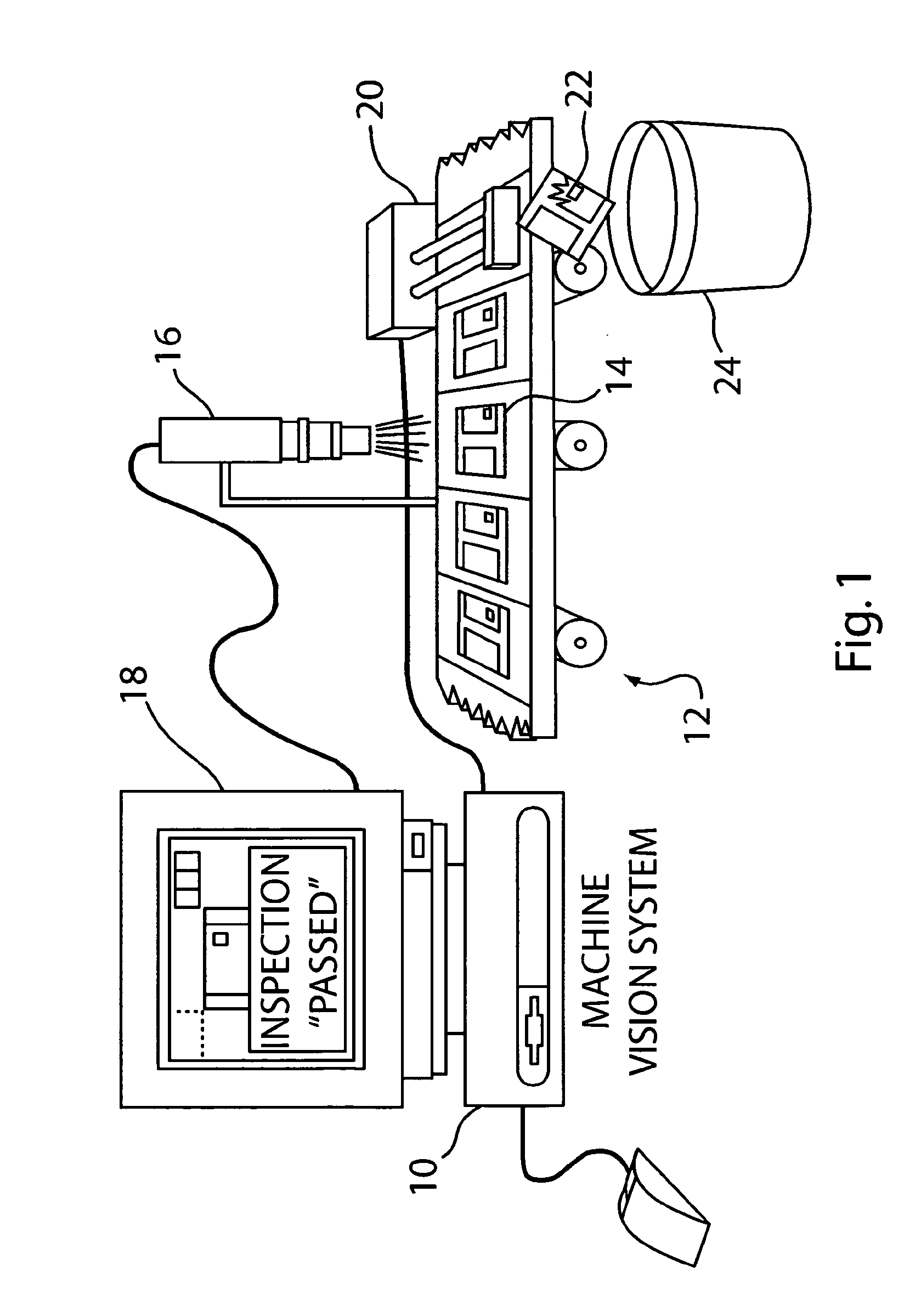
[0023]FIG. 1 depicts an illustrative machine vision industrial application adapted to perform methods of pattern location according to the present invention.

[0024]Pattern location is a common machine vision process used for inspection, alignment and registration, and as an initial subprocess to more complex machine vision analysis processes. Pattern location requires training the system with a model during a set-up or configuration phase, followed at run-time by finding the model in the image.

[0025]Referring to FIG. 1, in accordance with the present invention, there is provided a visual inspection system that can be employed by, for example a machine vision for aid in making decisions and providing information about objects in an inspection process such as commonly occur in automated industrial manufacturing. For example, the visual inspection system can be employed in a machine vision system 10 for a manufacturing line such as manufacturing line 12, as shown in FIG. 1. Using the in...


PUM


Abstract

Machine vision tools are applied to color images using methods that that utilize an optimized spectrum of the color information. Such methods include full color normalized correlation techniques and methods to convert color images to greyscale using weighting factors that maximize color contrast in a corresponding greyscale image.

Description

BACKGROUND OF THE INVENTION[0001]This invention relates to machine vision analysis of images, and specifically, to methods for finding an object in an image using color images.[0002]Machine vision is a term that generally refers to computer-based analysis of images to provide visual sensory input to industrial processes, such as inspection, automated handling, and process control. Machine vision is performed through the application of digital image processing software on image data acquired by digital imaging equipment, such as CMOS or CCD cameras.[0003]Digital image processing typically includes numerous computations to locate and assess characteristics of image features, including comparisons to known models. Methods for performing such a comparison are generally referred to as pattern location.[0004]One commonly used rudimentary method for pattern location is generally known as blob analysis. In this method, the pixels of a digital image are classified as “object” or “background”...

Claims


Application Information

Patent Timeline
IPC IPC(8): G06K9/00G06V10/28
CPCG06K9/6203G06K9/38G06V10/28G06V10/7515
Inventor WALLACK, AARON S.MICHAEL, DAVID
Owner COGNEX TECH & INVESTMENT
Why Eureka
Eureka Blog
Learn More