Method of raising a building

Active Publication Date: 2009-06-04
SO L E S SOC LAVORI EDILI E SERBATOI +1
View PDF16 Cites 21 Cited by
  • Summary
  • Abstract
  • Description
  • Claims
  • Application Information

AI Technical Summary

Benefits of technology

[0007]It is an object of the present invention to provide a method of raising a buildin

Problems solved by technology

In the case of a very large building and/or unusual structural situations, the above known methods leave room for improvement, in that, a

Method used


Image

  • Method of raising a building
  • Method of raising a building
  • Method of raising a building

Examples


Example

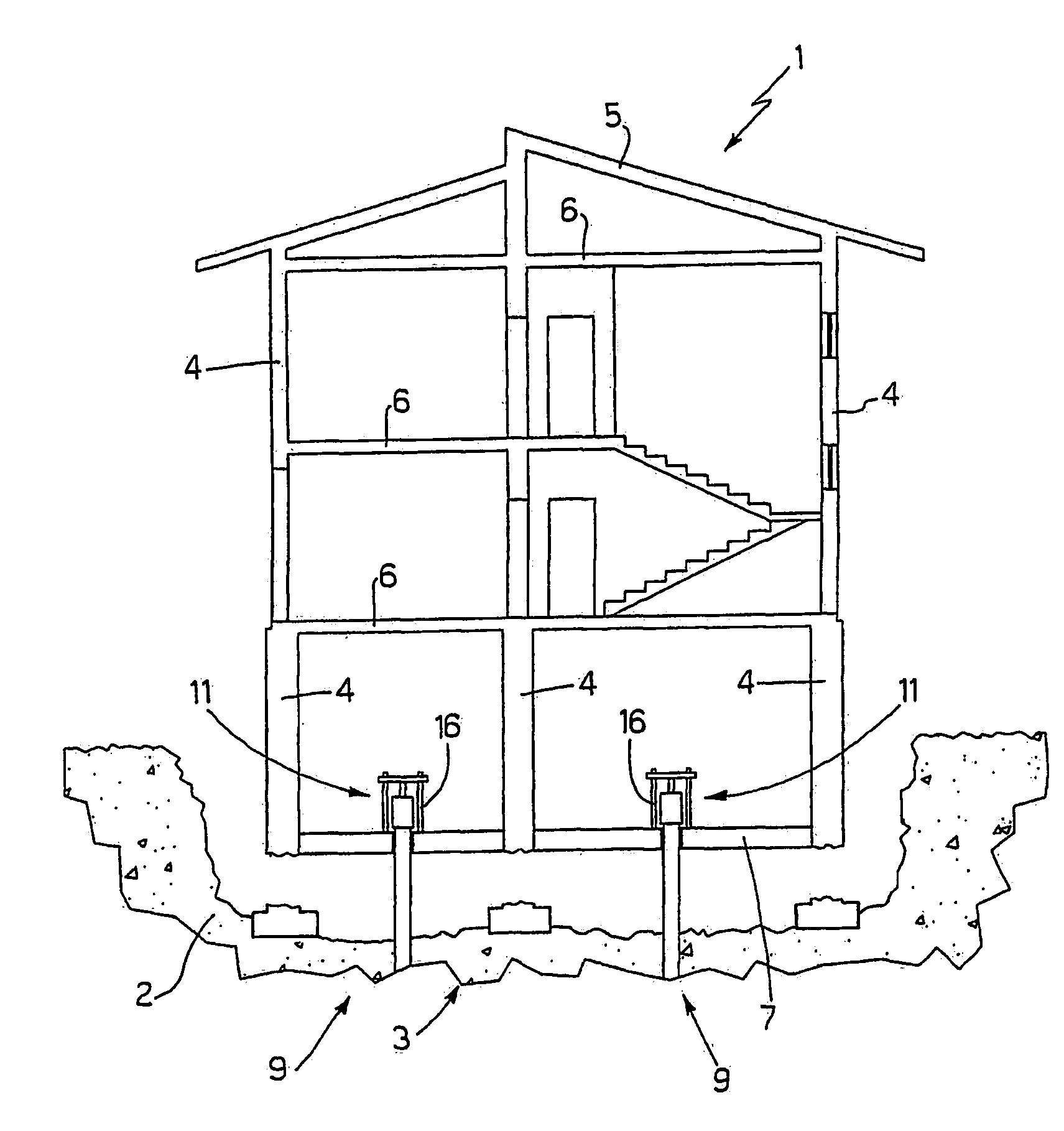
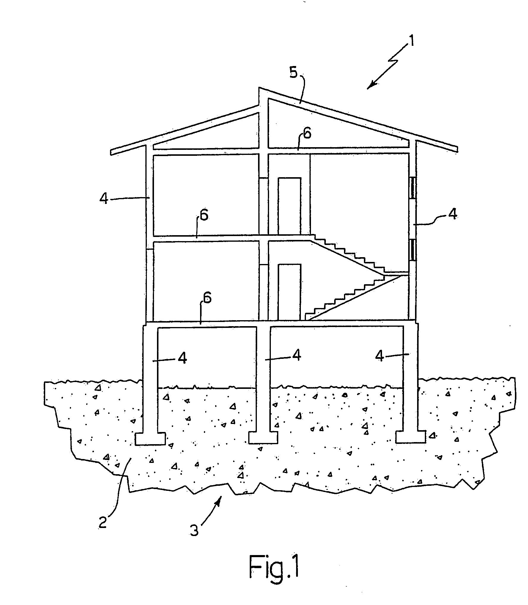
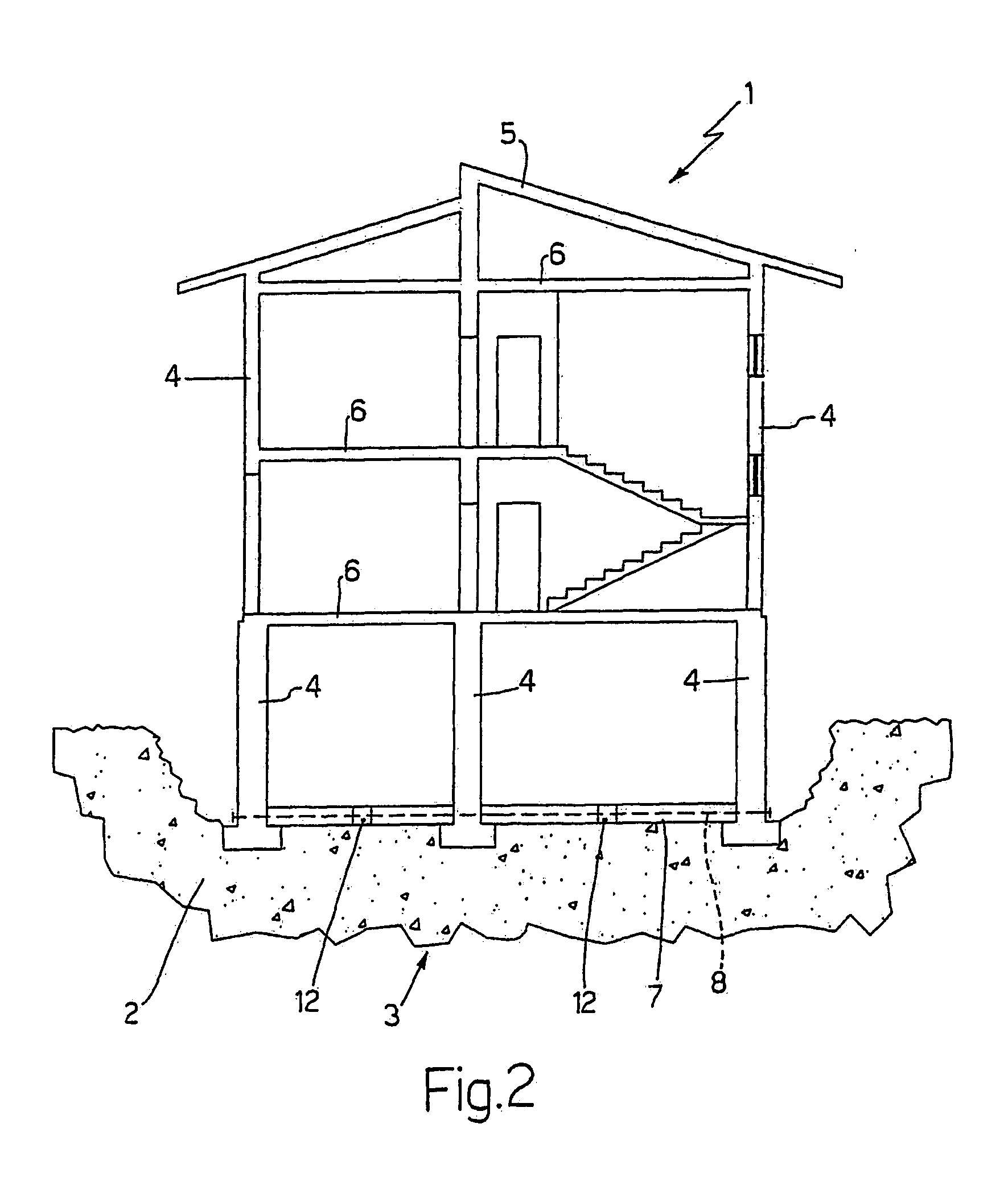
[0020]Number 1 in FIG. 1 indicates as a whole a building resting on the ground 2 on a foundation 3, and to be raised with respect to ground 2. Building 1 comprises a number of supporting walls 4, each of which rests on foundation 3, extends up to a roof 5, and supports four floors 6. Building 1 also comprises a number of nonsupporting walls not shown in the accompanying drawings.

[0021]First, a survey of building 1 is conducted to determine the value and distribution of the masses constituting building 1, and which comprises floor plans of the various floors, and drawings of all the walls, showing door and window openings and any damage to the walls. Given the thickness and density of the walls, it is possible to determine their weight and weight distribution.

[0022]A static analysis of building 1 is also made to ensure it is capable of safely withstanding lifting-induced stress; and, if necessary, building 1 may be consolidated and strengthened before it is raised.

[0023]A survey of g...


PUM


Abstract

A method of raising a building with respect to the ground; the method including the steps of: forming a mat having a number of through holes; inserting a foundation pile through each hole; fitting each foundation pile with a lifting device; exerting thrust on the foundation piles by means of the lifting devices to raise the building with respect to the ground; and fixing each foundation pile axially to the mat once the building is raised; the lifting devices are divided into three equivalent, symmetrical, independent work groups; and the lifting devices of one work group at a time are activated simultaneously, so that the building is raised isostatically, by simultaneously activating the lifting devices of one work group at a time, while the lifting devices of the other two work groups are left idle.

Description

TECHNICAL FIELD[0001]The present invention relates to a method of raising a building.BACKGROUND ART[0002]In the building industry, it is often necessary to raise a building, e.g. to raise a riverside or seafront building above flood or high-tide level. A typical example of this is the city of Venice, where the ground floors of buildings are regularly flooded by so-called “high-water phenomena”.[0003]Alternatively, a building may be raised to build a basement underneath, in situations in which excavating underneath the building is undesirable or impossible, or to increase the height, to make full use, of a floor.[0004]Patent IT1303956B proposes a method of raising a building, whereby a new foundation is built comprising a number of through holes; and, for each through hole, a connecting member fixed to the foundation, adjacent to the hole, and projecting at least partly upwards; a pile is then inserted through each hole, and a first thrust is applied statically to the pile to drive i...

Claims


Application Information

Patent Timeline
IPC IPC(8): E02D35/00
CPCB66F7/20E04G23/06E02D35/00E02D27/48E04G23/065
Inventor COLLINA, VINCENZOMARABELLO, GIOACCHINOZAGO, ROBERTOZAMBIANCHI, LAMBERTO
Owner SO L E S SOC LAVORI EDILI E SERBATOI
Why Eureka
Try Eureka